Group B Water System
Design Guidelines
Design Information for New or Expanding
Group B Water Systems.
DOH 331-467
Revised, September 2018

Group B Water System Design Guidelines (DOH 331-467) Page i
September 2018
Table of Contents
TABLE OF CONTENTS .............................................................................................................................. I
CHAPTER 1 INTRODUCTION ............................................................................................................ 3
1.0 PURPOSE AND SCOPE .............................................................................................................................. 4
1.1 “MUST” VERSUS “SHOULD” ................................................................................................................... 4
1.2 JURISDICTION AND STANDARDS ............................................................................................................. 5
1.3 BASIC DESIGN STANDARDS.................................................................................................................... 6
1.4 PROJECT SUBMITTALS ............................................................................................................................ 7
1.5 REQUIREMENTS FOR A PROFESSIONAL ENGINEER .................................................................................. 8
1.6 OTHER REFERENCED DOCUMENTS AND STANDARDS ............................................................................. 9
1.7 DEPARTMENT OF HEALTH CONTACTS .................................................................................................... 9
CHAPTER 2 BASIC WATER SYSTEM INFORMATION .............................................................. 10
2.0 PUBLIC WATER SYSTEM CLASSIFICATION ........................................................................................... 10
2.1 APPLICABILITY .................................................................................................................................... 13
2.2 PROJECT APPROVAL APPLICATION FORM ............................................................................................ 14
2.3 SERVICE AREA MAP AND LOCATION ................................................................................................... 14
2.4 PUBLIC WATER SYSTEM COORDINATION ACT ..................................................................................... 14
2.5 SATELLITE MANAGEMENT AGENCY .................................................................................................... 15
2.6 DISCLOSURE ON PROPERTY TITLE ........................................................................................................ 15
2.7 PROTECTIVE COVENANTS .................................................................................................................... 16
2.8 WATER USERS’ AGREEMENT ............................................................................................................... 16
2.9 WATER FACILITIES INVENTORY ........................................................................................................... 16
2.10 EASEMENTS ..................................................................................................................................... 16
CHAPTER 3 ESTIMATING WATER DEMANDS ........................................................................... 17
3.0 WATER RIGHTS .................................................................................................................................... 17
3.1 RESIDENTIAL WATER DEMAND ........................................................................................................... 19
3.2 NONRESIDENTIAL WATER DEMAND .................................................................................................... 20
3.3 EXAMPLES ........................................................................................................................................... 22
3.4 FIRE SUPPRESSION ............................................................................................................................... 25
CHAPTER 4 SOURCES OF SUPPLY ................................................................................................ 26
4.0 WELL CONSTRUCTION ......................................................................................................................... 26
4.1 SOURCE WATER QUANTITY ................................................................................................................. 27
4.2 SOURCE WATER QUALITY ................................................................................................................... 29
4.3 SOURCE PROTECTION ........................................................................................................................... 31
4.4 INTERTIES ............................................................................................................................................ 31
CHAPTER 5 WELL PUMP, BLADDER TANKS, AND PUMP HOUSE ....................................... 34
5.0 WELL PUMP ......................................................................................................................................... 34
5.1 PRESSURE TANKS ................................................................................................................................. 43
5.2 PUMP HOUSE DESIGN AND CONSTRUCTION RECOMMENDATIONS ........................................................ 48
5.3 WELL AND PUMP HOUSE DETAILED DRAWINGS AND SPECIFICATIONS ................................................ 48
CHAPTER 6 PIPING DESIGN AND CONSTRUCTION ................................................................. 50
6.0 PIPING MATERIAL ................................................................................................................................ 50
6.1 PIPE BURIAL, BEDDING, AND THRUST BLOCKS .................................................................................... 51
6.2 ISOLATION VALVES, FLUSHING HYDRANTS, AND AIR RELEASE VALVES ............................................ 51
6.3 DISTRIBUTION SYSTEM PIPELINE EASEMENTS ..................................................................................... 52
6.4 PRESSURE AND LEAKAGE TEST ............................................................................................................ 52
6.5 DISINFECTION ...................................................................................................................................... 52
6.6 MICROBIOLOGICAL TESTING ................................................................................................................ 52
6.7 SEPARATION FROM NONPOTABLE PIPING SYSTEMS ............................................................................. 53

Group B Water System Design Guidelines (DOH 331-467) Page ii
September 2018
6.8 SERVICE CONNECTIONS ....................................................................................................................... 53
6.9 INDIVIDUAL PRESSURE REDUCING VALVES ......................................................................................... 54
6.10 DISTRIBUTION SYSTEM DETAIL DRAWINGS AND SPECIFICATIONS .................................................. 54
CHAPTER 7 ATMOSPHERIC STORAGE TANKS ......................................................................... 56
7.0 OPERATING STORAGE VOLUME ........................................................................................................... 56
7.1 EQUALIZING STORAGE VOLUME AND ELEVATION ............................................................................... 57
7.2 STANDBY STORAGE VOLUME .............................................................................................................. 58
7.3 FIRE SUPPRESSION ............................................................................................................................... 58
7.4 DEAD STORAGE VOLUME .................................................................................................................... 59
7.5 TOTAL STORAGE VOLUME ................................................................................................................... 59
7.6 RESERVOIR DESIGN REQUIREMENTS AND CONSIDERATIONS ............................................................... 60
CHAPTER 8 BOOSTER PUMPS ........................................................................................................ 63
8.0 BOOSTER PUMP STATION DETAILED DRAWINGS AND SPECIFICATIONS ............................................... 63
CHAPTER 9 TREATMENT FOR SECONDARY CONTAMINANTS........................................... 65
9.0 SECONDARY TREATMENT DESIGN ....................................................................................................... 65
9.1 COMMON STRATEGIES FOR IRON AND MANGANESE REMOVAL ........................................................... 65
9.2 SECONDARY TREATMENT DETAIL DRAWINGS AND SPECIFICATIONS ................................................... 65
9.3 CONSUMER NOTIFICATION REQUIRED ................................................................................................. 66
9.4 TREATMENT WASTE DISPOSAL ............................................................................................................ 66
CHAPTER 10 FINANCIAL VIABILITY ........................................................................................ 68
10.0 COMPLETING THE FINANCIAL VIABILITY WORKSHEET ................................................................... 68
10.1 DISCLOSURE TO CUSTOMERS .......................................................................................................... 68
10.2 EXPLANATION OF TERMS ................................................................................................................ 69
APPENDICES ............................................................................................................................................. 73
To request this document in another format, call 1-800-525-0127. Deaf or hard of hearing customers,
please call 711 (Washington Relay) or email doh.informatio[email protected]. If in need of translation
services, call 1-800-525-0127.

Group B Water System Design Guidelines (DOH 331-467) Page 3
September 2018
CHAPTER 1 Introduction
The Washington State Department of Health, Office of Drinking Water (DOH) developed these
Group B Water System Design Guidelines. They explain how to design Group B water systems
to ensure safe, adequate, and reliable drinking water for those the water system will serve. They
will also help you prepare a complete Group B Design Workbook, which you must submit for
approval before you start constructing your new or expanding Group B water system.
We recommend you review these guidelines before beginning your Group B water system
design. We organized the chapters by subject matter (basic water system information, estimating
water demand, source of supply, and so forth).
The Appendices contain helpful references, such as how to perform and report the results of a
well pump test, using special well pump controls, an outline for a water users’ agreement, and
how to complete an inventory of your proposed water system.
Group B information is available on our website at
doh.wa.gov/CommunityandEnvironment/DrinkingWater/WaterSystemAssistance/GroupB.
Group B Design Workbook
These guidelines will help you prepare a complete Group B Design Workbook (DOH 331-468)
that meets each applicable requirement of chapter 246-291 WAC in an efficient manner that
reflects sound water system design practices and public health principles. You will submit the
workbook to the reviewing authority for approval. You can view, download, or order a CD of the
workbook from DOH at http://doh.wa.gov/odwpubs/.
Make copies of all plans, design drawings, worksheets, equipment information, operations and
maintenance manuals, legal documents, and forms before you send your completed workbook to
the reviewing agency. Keep this information with your other project documents. It will help you
and others manage and operate the new water system successfully. Keep your copy of these
guidelines; do not submit them with your workbook.
Online Group B Resources
We developed the following Group B resources to help you from pre-approval of your water
system design through operation and maintenance.
• All the forms you need to meet the submittal requirements for a new or expanding
Group B water system.
• Guidance to help you operate and maintain your small system. We urge you to
review this information before you begin operating your new or expanded system.
They are online at
doh.wa.gov/CommunityandEnvironment/DrinkingWater/WaterSystemAssistance/GroupB/Resources.

Group B Water System Design Guidelines (DOH 331-467) Page 4
September 2018
Regulations
Before starting your design, become familiar with Washington’s Group B water system rule
(chapter 246-291 WAC) and the information in these guidelines. The Group B rule is online at
doh.wa.gov/CommunityandEnvironment/DrinkingWater/RegulationandCompliance/Rules.
If you have questions about these guidelines or the State Board of Health rules on Group B
Water Systems (chapter 246-291 WAC), contact the state Department of Health (see Table 1.1)
or your local health jurisdiction (LHJ). Contact information for LHJs is at
doh.wa.gov/AboutUs/PublicHealthSystem/LocalHealthJurisdictions.
1.0 Purpose and Scope
These guidelines will help developers, locally certified designers, and design engineers meet the
approval requirements for a new or expanding Group B public water system by:
• Establishing uniform and simplistic concepts for very small water system designs.
• Meeting the submittal requirements described in chapter 246-291 WAC.
• Helping DOH regional engineers and LHJ reviewers to apply consistent review
procedures.
1.0.1 Expanding Systems
Unless otherwise noted, these guidelines apply to new and expanding systems. For example,
suppose your successfully operating existing Group B water system was approved to serve four
residential connections. To expand the system to serve additional residences, your existing
system must meet all current regulatory requirements, regardless of past approval (chapter 246-
291 WAC). You must prepare a complete workbook for review and approval by the reviewing
authority before expanding your water system.
Designers may use design approaches other than those in these guidelines as long as the alternate
approach does not conflict with chapter 246-291 WAC and they give appropriate justification for
taking an alternate approach.
1.1 “Must” versus “Should”
Throughout these guidelines we use the terms “must,” “will,” “shall,” or “required” when
design practice is sufficiently standardized to permit specific delineation of requirements, or
where safeguarding the public health justifies definitive criteria or action (for example, when a
state statute or rule mandates a requirement). The terms “should” or “recommend” indicate
procedures, criteria, or methods that are not required. You can approach these with some degree
of flexibility. Designers and design engineers need to explain the basis of the altered approach
or, in specific circumstances, why another approach may be more applicable.

Group B Water System Design Guidelines (DOH 331-467) Page 5
September 2018
1.2 Jurisdiction and Standards
Many LHJs assist DOH with at least some Group B drinking water program administration.
Others direct the Group B program within their jurisdictions, including approval of Group B
water system designs. In these guidelines, the term "department" refers to the agency that is
responsible for reviewing and approving a Group B water system design in the particular county.
1.2.1 Reviewing Authority
An LHJ has authority to adopt and implement its own Group B regulations, if they are at least as
stringent as chapter 246-291 WAC. Before beginning your Group B workbook, we strongly
recommend that you contact your LHJ to ask:
1. Is it the LHJ or DOH that is responsible for reviewing and approving the Group B
workbook? If the LHJ is responsible, you must submit the completed Group B workbook
to the LHJ for approval.
2. Does the LHJ implement its own local Group B drinking water program? If so, ask
for a copy of their rules and design standards. They could specify available design
options, who can prepare the design, and the available regulatory waivers.
3. Does the LHJ regulate one- or two-connection Group B systems? (Ask if you intend
to construct a one- or two-connection Group B water system).
We based statements in these guidelines on the requirements and limitations in chapter 246-291
WAC. Your LHJ may adopt its own regulations or enter into a Joint Plan of Responsibility with
DOH that offer broader design options, allow for certain waivers, or impose increased regulation
(WAC 246-291-030 (1)(a)). Moreover, if your LHJ implements its own local Group B drinking
water program it may develop its own accompanying design guidelines and Group B design
workbook.
1.2.2 Project Location
The location of your project affects whether you can create a new Group B water system and the
standards that apply to its design and approval. Before beginning your Group B design, we
strongly recommend that you ask the reviewing authority whether the location of your
proposed Group B water system is in:
1. An area the Department of Ecology has closed or established limits to all future
appropriation of groundwater, including gallon per day limits on small
groundwater withdrawals that are normally exempt from the water right permitting
process. If so, this could significantly affect the feasibility, scope, cost, and timing of
your project.
2. A critical water supply service area, as established under the Public Water System
Coordination Act of 1977. If so, you must request service from the existing water utility
serving the area of your proposed Group B water system.
3. An area served by one or more Satellite Management Agency (SMA). If so, an
available SMA must own, or manage and operate your proposed Group B water system
before DOH can approve the water system.
4. A tribal reservation. If so, contact the local health jurisdiction and the tribe for guidance
on approval requirements. DOH has no authority to approve Group B water systems
located entirely within a tribal reservation.

Group B Water System Design Guidelines (DOH 331-467) Page 6
September 2018
1.3 Basic Design Standards
The following standards apply to DOH approval of a Group B water system workbook under
chapter 246-291 WAC. If your LHJ implements its own local Group B drinking water program it
may have its own accompanying design guidelines and Group B design workbook. (WAC 246-
291-030 (1)(a)). Ask your LHJ whether it adopted a set of regulations that affect the standards
for design approval.
1. No supply source will be approved other than a drilled well that meets the requirements
of chapter 173-160 WAC, or an agency-approved intertie with an approved Group A or
Group B water system (WAC 246-291-125). New or expanding Group B systems cannot
use a lake, river, spring, dug well, groundwater under the direct influence of surface
water (GWI), rainfall catchment, or seawater source (WAC 246-291-125).
2. No supply source for a new or expanding Group B water system that exceeds a primary
drinking water standard (such as nitrate, arsenic, coliform) will be approved (WAC 246-
291-125(1) and -170(5)).
3. An LHJ or DOH must inspect the location (“well site”) of any existing or proposed well.
You must submit the inspector’s written well site inspection report with the water system
workbook (WAC 246-291-125(3)).
4. Applicants for a new or expanding water system must receive written approval of the
workbook from the reviewing authority before starting any construction (WAC 246-291-
120(1)).
5. Unless the proposal meets the exemption criteria for an engineer, new and expanding
Group B water systems must be designed by a professional engineer licensed in
Washington State (WAC 246-291-120(3) and (4)). Throughout these Guidelines, we cite
“may require a professional engineer,” in recognition of the exemption criteria. Designers
should note that a professional engineer must prepare and submit the workbook
whenever DOH is the reviewing authority (WAC 246-291-120(3) and (4)).
6. New or expanding water systems designed and intended to serve 10 or more dwelling
units must follow the Group A public water system approval process (WAC 246-291-
200(2)).
7. The design must demonstrate source capacity of at least 750 gallons per day per dwelling
unit for systems located west of the Cascade Mountain crest, and 1,250 gallons per day
per dwelling unit east of the Cascade Mountain crest (WAC 246-291-125(4)).
8. If an SMA is available in the location of a new Group B water system, then the workbook
must document that an SMA will either own or manage and operate the water system
(WAC 246-291-090). This requirement does not apply to an existing Group B water
system seeking to expand its number of approved connections.
9. If a proposed Group B water system is in a Critical Water Supply Service Area, then the
workbook must show that you requested water service from the water utility operating in
the area of the proposed system (WAC 246-291-090). This requirement does not apply
to an existing Group B water system seeking to expand its number of approved
connections if the new connections are in the Group B’s existing service area.
10. Conducting a well-site inspection and undertaking review of a new or expanding
Group B water system workbook are fee-supported activities. The LHJ or DOH will
charge fees. For DOH review fees, see WAC 246-290-990.

Group B Water System Design Guidelines (DOH 331-467) Page 7
September 2018
1.4 Project Submittals
You must submit a complete Group B workbook to DOH for
written approval before construction begins whenever a new
Group B water system is being developed, and whenever an
existing Group B water system seeks an increase the number
of approved connections (an expanding system) (WAC 246-
291-120(1)).
Construction of a new or expanding water system may be
subject to local permits or approvals, including a local
government finding of physical and potable water availability.
Compliance with DOH requirements does not guarantee full
compliance with local rules. You must also satisfy and follow
local approval process. You can get information about local
approval processes from most county building departments and environmental health programs.
DOH’s review of your water system design will not confer or guarantee any right to a specific
quantity of water. We base our review on your representation of available water quantity. If the
Department of Ecology, a local planning agency, or other authority responsible for determining
water rights and water system adequacy determines that you have use of less water than you
represent, the number of approved connections may be reduced commensurate with the actual
amount of water and your legal right to use it.
If your design submittal meets all applicable requirements, you will receive an approval letter.
The letter will refer to the lot(s) the approved system serves, and include a statement such as:
The department’s approval of your water system design does not confer or guarantee
any right to a specific quantity of water. The approved number of service connections
is based on your representation of available water quantity. If the Washington
Department of Ecology, a local planning agency, or other authority responsible for
determining water rights and water system adequacy determines that you have use of
less water than you represented, the number of approved connections may be reduced
commensurate with the actual amount of water and your legal right to use it.
The designer must verify that construction was completed according to the approved plans and
specifications. The designer or inspecting engineer must complete a Construction Completion
Report and submit it to DOH within 60 days of project completion and before providing water to
the public (WAC 246-291-120(5)). The Construction Completion Report form is online at
doh.wa.gov/CommunityandEnvironment/DrinkingWater/WaterSystemAssistance/GroupB/Design.
If the designer considers significant changes from the approved project plans during
construction, the designer must submit to DOH a description of the changes and justification for
them. We must approve the proposed changes before they are constructed (WAC 246-291-120
(6)). Significant change means:
• The size, number, elevation, depth, material, and/or capacity of water system
components are different from those described in the approved workbook.
• Testing procedures differ from those described in the approved workbook.
See Figure 1.1 for the project design, submittal, review, and construction process.

Group B Water System Design Guidelines (DOH 331-467) Page 8
September 2018
Figure 1.1: Design, Submittal, Review, and Construction Process
1.5 Requirements for a Professional Engineer
The design report workbook must be prepared by a professional engineer licensed in
Washington State (chapter 18.43 RCW (WAC 246-291-120 (3)). Exceptions to the professional
engineer requirement are only possible when the LHJ has accepted primary responsibility for
review and approval of Group B design report workbooks, and the local Board of Health rules
provide an exception to the professional engineer requirement, and all of the following design
conditions are satisfied:
• No variable speed pumps.
• No fire flow.
• No special hydraulic considerations.
• No atmospheric storage in which the bottom elevation of the storage reservoir is below
the ground surface.
• No more than nine service connections to be served.

Group B Water System Design Guidelines (DOH 331-467) Page 9
September 2018
1.6 Other Referenced Documents and Standards
We cite other waterworks-related laws, guides, standards, and documents in these guidelines to
provide appropriate references. These references form a part of these guidelines, but it is not our
intent to duplicate them.
All water system designs must comply with locally adopted national model codes, such as the
International Building Code (IBC) and Uniform Plumbing Code (UPC), and conform to other
applicable industry standards and guidance, such as that from the American Water Works
Association (AWWA), American Society of Civil Engineers (ASCE), and the American Public
Works Association (APWA) (WAC 246-291-200(1)).
1.7 Department of Health Contacts
The designer or design engineer should contact us with questions or design concerns. DOH
contact information is in Table 1.1. You can get contact information for your LHJ from your
local information sources or online at
doh.wa.gov/CommunityandEnvironment/DrinkingWater/OfficesandStaff.
Table 1.1
Office of Drinking Water Regional Offices
Eastern Region
Serving
Drinking Water Eastern Regional Office
16201 E. Indiana Ave., Suite 1500
Spokane Valley, WA 99216
Phone: 509-329-2100
Fax: 509-329-2104
TDD Relay: 1-800-833-6388
Adams, Asotin, Benton, Chelan, Columbia,
Douglas, Franklin, Ferry, Garfield, Grant,
Kittitas, Klickitat, Lincoln, Okanogan, Pend
Oreille, Spokane, Stevens, Walla Walla,
Whitman, and Yakima counties.
Northwest Region
Serving
Drinking Water Northwest Regional Office
PO Box 47800
Olympia WA 98504
Phone: 253-395-6750
Fax: 253-395-6760
TDD Relay: 1-800-833-6388
Island, King, Pierce, San Juan, Skagit,
Snohomish, and Whatcom counties.
Southwest Region
Serving
Drinking Water Southwest Regional Office
Physical: 243 Israel Road
Tumwater, WA 98501
Mailing: P O Box 47823
Olympia, WA 98504-7823
Phone: 360-236-3030
Fax: 360-664-8058
TDD Relay: 1-800-833-6388
Clallam, Clark, Cowlitz, Grays Harbor,
Jefferson, Kitsap, Lewis, Mason, Pacific,
Skamania, Thurston, and Wahkiakum counties.

Group B Water System Design Guidelines (DOH 331-467) Page 10
September 2018
CHAPTER 2 Basic Water System Information
Chapter 2 covers the basic water system information required for most submittals. This includes
the location, size, system classification, and future ownership and management of the water
system.
2.0 Public Water System Classification
Different types of water systems are subject to different regulations. Start by establishing
whether your proposed water system is a public water system. Next, determine the system
classification.
A public water system is any system providing water for human consumption, excluding a
system serving only one single-family residence, or a system with four or fewer service
connections, all of which serve residences on the same farm. See the complete definition in
WAC 246-291-010.
We base public water system classification on population and number of connections
served. There are two classifications: Group A and Group B.
• Group A water systems serve 15 or more connections, OR 25 or more people per day
for 60 or more days within a calendar year.
• Group B water systems serve fewer than 15 service connections and
o Fewer than 25 people per day, OR
o Twenty-five or more people per day for fewer than 60 days per year provided the
system doesn’t serve 1,000 or more people for two consecutive days (WAC 246-
291-005).
These guidelines cover the design standards applicable to Group B public water systems.
2.0.1 Connections Served
Determine the total number of connections by counting each single-family home, each dwelling
unit in a multifamily building, and each nonresidential building that the water system serves. The
complete definition of “service connection” is in WAC 246-291-010.
For the purposes of assessing the number of connections associated with a Group B design, an
Accessory Dwelling Unit (ADU) is considered a separate dwelling unit if it is located outside
and separate from the single family residence. An ADU located within the single-family
residence, such as a mother-in-law apartment in the basement, is not considered a separate
connection.
In the following examples, we applied the definitions of service connection in WAC
246-291-010 and how we count ADUs.
• A system serving two duplexes and two single-family homes serves a total of six
dwelling units. Each dwelling unit is considered a separate connection.
• A system serving four single-family homes, each with an accessory dwelling unit
incorporated into the main structure of the home, serves a total of four dwelling units, and
therefore four connections.

Group B Water System Design Guidelines (DOH 331-467) Page 11
September 2018
• A system serving four single-family homes, each with an accessory dwelling unit built as
a separate structure on the same parcel, serves a total of eight dwelling units and,
therefore, eight connections.
• A system serves three single-family homes. One home has an attached shop with piped
water that serves as a place of employment for people from outside the home. The other
two homes each have a separate structure with piped water that serves as a retail or
commercial business open to customers or clients. This system serves three dwelling
units plus three nonresidential connections, for a total of six connections.
DOH will not recognize ADUs an applicant claims as a dwelling unit unless:
• The proposal assumes ADUs on each lot served.
• Zoning permits the construction of separate-structure ADUs on each lot served.
• The property title for each lot discloses the water system is designed to supply a
separate-structure ADU on each lot. See Section 2.6.
Section 2.0 of the design workbook explains how to report the number of residential and
nonresidential connections your Group B water system will serve.
2.0.2 Population Served
The population you must count is the number of people that have access to piped water for
human consumption. The population served is either residential (people living in a residence), or
nonresidential (tourists, customers, employees) entering the premises and given the opportunity
to access tap water. Here are two examples of estimating population based on access.
A Post Office has a restroom and coffee bar or sink located behind the customer counter,
where only employees can access these facilities. There is no water service provided in
the visitor or customer service area of the Post Office. The number of people served by
this water system is the number of people who work at the Post Office. Do not count
visitors.
A commercial business has a rest room accessible to the public. The estimated service
population should be based on the estimated number of customers plus employees. Count
everyone expected to enter the business.
2.0.2.1 Residential Population
For the purposes of design, and to identify the appropriate water system approval standards,
2.5 residents must be assigned to each dwelling unit (WAC 246-291-200(2)). Local health
jurisdictions cannot waive or modify this population standard. Therefore, if your
proposed system serves 10 or more dwelling units, we will review your proposal under the
approval standards for Group A public water systems (chapter 246-290 WAC). Group A
system approval standards are different from Group B system approval standards. See
Section 2.0.3 below.
2.0.2.2 Nonresidential Population
A water system designed to serve 25 or more people for 60 or more days per year will be
considered a Group A water system (WAC 246-290-005). Our data system uses the
information you provide on your Water Facilities Inventory Form (WFI) to calculate a daily

Group B Water System Design Guidelines (DOH 331-467) Page 12
September 2018
average for each calendar month. (See Section 2.9.) If your expected average daily service
population for two or more calendar months exceeds 24 people, we will review your proposal
under the approval standards for Group A public water systems. See Section 2.0.3 below.
2.0.3 Application of Group A Public Water System Approval Standards
If we conclude that the scope of your project places your proposed water system into the Group
A classification, we will return your Group B workbook to you with an explanation. Contact
your DOH regional office to discuss the conclusion and, as applicable to your circumstance, the
Group A public water system approval process.
2.0.4 Applying Under False Pretense
We are aware of the incentive for applicants to submit false or misleading information
intentionally presenting an application for a Group A water system when the intended
development actually meets the definition of a Group B water system. For example:
An applicant plans a four-lot subdivision to be served by a new Group B water
system. The Department of Health is the approving authority in this jurisdiction.
Before submitting the Group B design for approval, the applicant drills and tests a
new well. The well produces a sufficient supply but exceeds the arsenic standard.
The Group B rule prohibits DOH from approving the source (chapter 246-291
WAC). The Group A rule does not prohibit DOH from approving this source if
arsenic treatment is designed and installed (chapter 246-290 WAC).
To create a pathway for project approval, the applicant claims the water system
will serve a fictitious commercial connection in addition to the four residences,
thus pushing the population above 24 people served at least 60 days per year. The
applicant claims the design is for a Group A water system.
Because the commercial connection never occurs, the system never becomes a Group A water
system and, therefore, the treatment process is never subject to any oversight. To protect public
health for the life of the water system, the state Board of Health adopted a rule allowing
treatment only if the approving authority grants a waiver (chapter 246-291 WAC). The
approving authority must have the resources and authority to oversee the treatment process to
ensure proper treatment for the life of the water system.
To prevent applicants from bypassing the rule by pretending to propose Group A systems, DOH
will require any applicant who claims a Group A commercial use associated with a Group B
residential development to submit detailed supporting documentation if a source exceeds a
primary drinking water quality standard.
Group B Water System Design Guidelines (DOH 331-467) Page 13
September 2018
2.1 Applicability
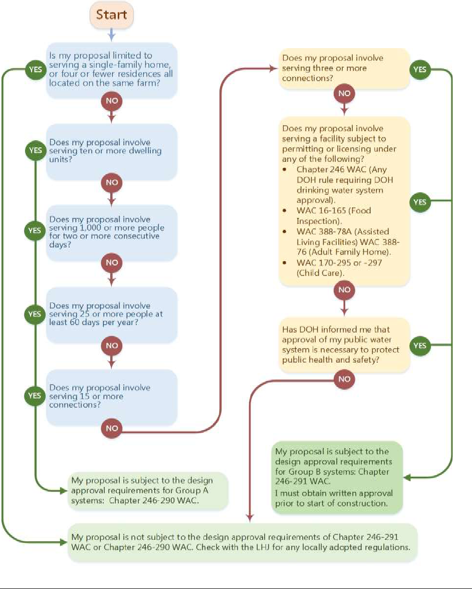
Based on public water system definitions and classifications (see Section 2.0), the following flow
chart will help you decide whether your proposed Group B public water system is subject to the
Group B design approval process. Please note that DOH is responsible for properly classifying
public water systems. Your use of this flow chart does not replace our responsibility.

Group B Water System Design Guidelines (DOH 331-467) Page 14
September 2018
2.2 Project Approval Application Form
On the Group B Project Approval Application Form, the designer provides the information
necessary to review and process the application properly. This information includes:
• Contact information for both the water system and the person submitting the
project.
• The number and type of connections the system serves or will serve.
• The type of project.
The Group B Project Approval Application Form is online at
doh.wa.gov/CommunityandEnvironment/DrinkingWater/WaterSystemAssistance/GroupB/Design.
2.3 Service Area Map and Location
Applicants for a new or expanding water system must also provide a scaled map of the proposed
service area (WAC 246-291-140(1)). You can use the same map submitted with a land use
application or one that is similarly detailed. The map you use should include the boundaries of
the proposed service area, roads, property lines, parcel numbers, and other features helpful in
locating the project and individual features. You can use the same map to show the proposed
distribution system, or use a separate map.
2.4 Public Water System Coordination Act
The Public Water System Coordination Act of 1977 (RCW 70.116) requires applicants seeking
development of a new public water system to determine whether the proposed system is in the
future service area of an existing utility. The intent of the Coordination Act is to avoid creating
new water systems whenever an existing water system is available and willing to provide
service.
If your project is in a Public Water System Coordination Act planning area, ask the
reviewing authority to identify the utility providing service. You must request water service
from that utility. If the utility can provide service in a timely and reasonable manner, you must
obtain water service from the utility and abandon plans to develop a new water system (WAC
246-291-090). This requirement does not apply to an existing Group B water system seeking to
expand its number of approved connections if the new connections are in the Group B’s existing
service area.
To ensure compliance with this statute, you must include a written record of the request for
water service and the water supplier’s written response to that request in your workbook
(WAC 246-291-120). An example of a letter requesting water service is in the Appendix A.
If your project is outside a Public Water System Coordination Act planning area, you may
develop a new water system. However, your application is subject to the Satellite Management
Agency requirement (WAC 246-291-090).

Group B Water System Design Guidelines (DOH 331-467) Page 15
September 2018
2.5 Satellite Management Agency
A Satellite Management Agency (SMA) is an individual, water system, or other entity approved
by DOH to own or operate public water systems on a regional or countywide basis. The law
requires an approved SMA to own or operate all new water systems if one is available (RCW
70.119A.060). The intent of the SMA requirement is to place ownership, or operations and
management, of all new public water systems in the hands of experienced water suppliers
whenever possible. This requirement does not apply to an existing Group B water system
seeking to expand its number of approved connections.
All counties have at least one approved SMA. You should choose the SMA that best meets your
needs. The current approved SMA list is online at
doh.wa.gov/Portals/1/Documents/4200/sma_list.pdf.
If your project is in the service area of one or more approved SMA, ask each one whether it is
available to provide ownership or management services to your proposed public water system.
An example of a letter requesting SMA services is in Appendix B.
You must either provide a copy of an SMA agreement with your project submittal or proof that
no approved SMA is available (WAC 246-291-090 and -120).
YES, an SMA is available to own the proposed water system or provide management
services. You must provide a copy of the agreement with the project submittal.
NO SMA is available. You must provide a written record of each SMA rejection with
your project submittal.
Your SMA may require you to submit to them your water system design for review and
acceptance before you submit your application to DOH for approval, particularly if the SMA will
become the owner of the new water system.
SMA operational and management services may include:
• Creating and updating standard operating procedure and routine maintenance procedures.
• Reviewing and updating water system governance documents, including policies.
• Input on capital investment and infrastructure planning.
• Budgeting assistance and billing services.
• Sampling and treatment plant (if any) data collection and evaluation.
• Periodic inspection of sanitary control area, reservoir, and other infrastructure.
• Input on water main break, pump, and power failure response protocols.
• Response to complaints, water outages, and water quality emergencies.
Please review our publication Choosing a Satellite Management Agency (DOH 331-604).
2.6 Disclosure on Property Title
You must record an informational notice on the title of each property your new water system
will serve (WAC 246-291-140(2)). A sample notice is in Appendix C. When submitting your
workbook to the reviewing authority, provide a copy of the content you will record on the title of
each property your water system will serve. List all parcel numbers available at the time you
submit your completed Group B design workbook. The actual recorded document must include
the actual parcel numbers the water system will serve.

Group B Water System Design Guidelines (DOH 331-467) Page 16
September 2018
Ask your County Auditor which form you should use to record notice to title.
2.7 Protective Covenants
Protective covenants are required to secure the area around a public drinking water supply from
future use and development that may threaten water quality and public health (WAC 246-291-
125(5)). Section 4.3 explains how to provide legal protection for the area around a public
drinking water supply well. When submitting your workbook to the reviewing authority, provide
a copy of the actual protective covenants on record with the County Auditor for each public
drinking water supply well.
These covenants must be on each of the affected properties, and filed with the County Auditor.
Check with your local government; you may be allowed to establish the covenant on the
subdivision plat.
Ask your County Auditor which format you should use to record the protective covenants for
each public drinking water supply well.
2.8 Water Users’ Agreement
You should establish a water users’ agreement for all new Group B water systems that include
residences or multiple property owners. All owners of the water system should sign the users’
agreement when the system is constructed and operational. An outline for a water users’
agreement is in Appendix D.
You may need to complete your water system design before you can finalize your draft water
users’ agreement.
2.9 Water Facilities Inventory
We recommend that you complete a Water Facilities Inventory Form (WFI) and include it with
your Group B workbook. To ensure the information in our data system is correct, answer all the
questions on the WFI. Instructions for Group B systems and a sample WFI form are in
Appendix E. If you plan to submit a workbook for an expanding Group B system, please submit
a marked-up version of your existing WFI form.
2.10 Easements
Your Group B workbook must show the location and dimension of easements you intend to
secure in order to adequately access and maintain all distribution system components, reservoirs,
wells, and pumping stations (WAC 246-291-120).

Group B Water System Design Guidelines (DOH 331-467) Page 17
September 2018
CHAPTER 3 Estimating Water Demands
Chapter 3 explains how to estimate expected Maximum Daily Demand (MDD) and Peak Hour
Demand (PHD) for your proposed water system. Engineers need water demand estimates to size
pumping equipment, transmission lines, distribution mains, and water storage facilities properly.
Demand estimates combined with information about your water supply source ensures the water
system can meet all the demands you expect it to meet over the year. Establishing the expected
MDD also determines whether you need a water right (RCW 90.44.050).
If you do need a water right, you must get the appropriate documents from the Department of
Ecology and include them in your workbook (WAC 246-291-125(3)).
If we believe you need a water right, but you don’t provide a copy with your submittal, we will
return your submittal to you. We will also explain our decision and recommend that you consult
with Ecology before resubmitting your design.
3.0 Water Rights
3.0.1 Water Right Permit Exempt Wells
The Department of Ecology administers the regulatory and permitting processes for water rights.
Newly designed Group B water systems may only obtain water from a groundwater source. Most
Group B water systems use the groundwater permit exemption (RCW 90.44.050) rather than
obtaining a permit from Ecology prior to using any water. There are different limitations on the
use of single domestic permit-exempt wells and group domestic permit-exempt wells.
Depending on the watershed, the owner of a group domestic permit-exempt well may withdraw
up to 5,000 gallons per day for group domestic uses. In addition, the owner may have a separate
allowance to irrigate lawns or noncommercial gardens. This separate irrigation allowance under
a group domestic permit-exempt well is not limited in terms of gallons per day; it is limited in
area. In addition to the 5,000 gallons per day limit for domestic use, the owner of a permit-
exempt well may withdraw any amount of water for irrigation not to exceed a combined total of
½ acre of lawns and noncommercial gardens, so long as the water is put to beneficial use.
Depending on the watershed, the owner of a single domestic well may have a specified
maximum daily withdrawal allowance different from the group domestic permit exemption. This
limitation may include all uses from the single domestic well, including irrigation.
For a complete description of the legal uses of a permit-exempt well, consult with Ecology about
water availability or visit
www.ecology.wa.gov/Water-Shorelines/Water-supply/Streamflow-restoration.
Permit-exempt wells are exempt only from the duty to obtain a permit to use groundwater, not
the other provisions of the Water Code. A right established through a permit-exempt well has the
same legal effect and must abide by the same requirements of prior appropriation and state
regulation of water resources as a permitted withdrawal. In other words, use of water from a
permit-exempt well must be regulated or curtailed, where necessary, to protect and prevent
impairment to more senior water rights. Even if your Group B water supply is a permit-exempt

Group B Water System Design Guidelines (DOH 331-467) Page 18
September 2018
well, it’s subject to curtailment if Ecology finds such action necessary to protect senior rights or
public waters. Local government must ensure an adequate potable water supply before issuing a
building permit. Before developing a permit exempt well check with local authorities on their
criteria for establishing an adequate potable water supply for your planned water system.
When assessing the need for a water right, you should assume that the domestic in-home
portion of your total system maximum daily demand (MDD) will be at least 350 gallons per
day (gpd) per dwelling unit. The domestic in-home demand is the portion of the total system
MDD that counts toward the 5,000-gallon-per-day limit described above.
3.0.2 Basins Closed to Further Appropriation
Ecology may close a basin to all further appropriation or establish reservations of water for
permit-exempt wells to protect senior water right holders and minimum instream values.
However, Ecology may create a pathway for an applicant of a new Group B water system to
follow a basin-specific process to secure permission to withdraw groundwater to supply the
system.
A basin-specific process may involve developing and implementing a mitigation plan. To
determine whether your project is located in a closed basin, contact Ecology. If so, you must
submit Ecology’s written permission to withdraw the groundwater you need with your Group B
water system workbook. While such permission, if granted, is not a “water right,” we apply the
requirement of WAC 246-291-125 (3) to such circumstances.
3.0.3 Multiple Permit-Exempt Withdrawals
The rule permits only one exemption for any one project, no matter how many wells and separate
small systems are established to supply the project.
If you intend to develop two or more separate, contiguous Group B water systems, you may not
have the legal authority to do so. Contact Ecology for assistance on this legal requirement.
3.0.4 Group B Applicants with a Water Right
A water right may state the number of connections that can be served. With one exception (see
below), the number of connections shown on the water right is a limiting factor for a new or
expanding system intended to serve fewer than 15 residential connections. In other words, if the
water right specifies that it applies to serving six single family homes, then the maximum
number of homes that can be served by the water system is six, even if the instantaneous and
annual volume permitted under the right could supply more homes.
The one exception is when an existing municipal water supplier owns the new or expanding
Group B system. Applicants who want to know whether their organization is a municipal water
supplier should contact their DOH regional office.
Group B Water System Design Guidelines (DOH 331-467) Page 19
September 2018
3.1 Residential Water Demand
3.1.1 Residential MDD
The MDD is the maximum single-day demand the water supply must meet. It consists of in-
home domestic demand (see Section 3.0.1), outdoor demand, nonresidential demand, and
distribution system leakage. It’s important to establish the proposed water system’s MDD before
you drill and test the water supply well.
WAC 246-291-125 (4) specifies the minimum source capacity and minimum MDD for
residential service connections (see Table 3.1).
Table 3.1
Standards for Minimum Source Capacity and
Minimum MDD for Residential Service Connections
County
Gallons per day per
dwelling unit
Clallam, Clark, Cowlitz, Grays Harbor, Island, Jefferson, King,
Kitsap, Lewis, Mason, Pacific, Pierce, San Juan, Skamania, Skagit,
Snohomish, Thurston, Wahkiakum, and Whatcom
750
Adams, Asotin, Benton, Chelan, Columbia, Douglas, Ferry,
Franklin, Garfield, Grant, Kittitas, Klickitat, Lincoln, Okanogan,
Pend Oreille, Spokane, Stevens, Walla Walla, Whitman, and
Yakima
1,250
Because residential MDD includes inside and outside uses, the actual demand could be
considerably higher than the minimum values listed in Table 3.1. In general, the demand for
water increases along with lot size, home size, and average summer temperatures. Other site-
specific considerations, such as the development’s Covenant, Conditions, and Restrictions; cost
of water; soil type; and irrigation system technology, may also affect water demand. The
designer and design engineer should strongly consider whether the minimum values in Table 3.1
are sufficient to meet the expected demands of future customers. The effect of under-estimating
the MDD includes low pressure, summertime water rationing, dissatisfied customers, and
increased vulnerability to backsiphonage of nonpotable water into the distribution system.
3.1.2 Residential PHD
It’s important to establish the peak hourly demand (PHD) before designing the system of wells,
pumps, pipes, and pressure tanks. The relationship between PHD, sustained well yield, and well
pump capacity will determine whether the proposed water system requires atmospheric storage
to supplement the supply source(s) to meet the expected PHD. See Chapter 5 for details.
Table 3.2 provides guidance on establishing the minimum PHD for residential demand. For the
same reasons cited in 3.1.1 above, the actual PHD of the customers your proposed Group B
system will serve could be considerably higher than the values in Table 3.2. The effect of under-
estimating the PHD includes low pressure, dissatisfied customers, and increased vulnerability to
backsiphonage of nonpotable water or other potential contaminants into the distribution system.

Group B Water System Design Guidelines (DOH 331-467) Page 20
September 2018
Table 3.2
Guide for Minimum Residential Peak Hourly Demand
Number of
dwelling units
Peak Hour Demand
(in gallons per minute)
2
23
3
26
4
28
5
31
6
34
7
36
8
39
9
41
Source: Adapted from DOH Water System Design
Manual.
3.2 Nonresidential Water Demand
3.2.1 Nonresidential MDD
Table 3.3 provides guidance on nonresidential average maximum daily demand (MDD). We use
the values here as guidance with the following assumptions:
• Unit nonresidential demand will vary little from day to day.
• MDD is based on a full facility (the campsite or hotel is fully occupied or the school is
operating at capacity).
Table 3.3
Guide for Nonresidential Water Demand
Type of Establishment
Maximum Daily
Demand
(in gallons per day)
Bathhouse (per bather)
10
Boardinghouse (per boarder)
Additional kitchen requirements for nonresident boarders
50
10
Camp:
Construction, semi-permanent (per worker)
Day, no meals served (per camper)
Luxury (per camper)
Resort, day and night, limited plumbing (per camper)
Tourist, central bath and toilet facilities (per person)
50
15
100 - 150
50
35
Factory (gallons per person per shift)
15 - 35
Highway rest area (per person)
5
Hotel:
Private baths (2 persons per room)
No private baths (per person)
50
50
Institution other than hospital (per person)
75 - 125
Laundry, self-serviced (gallons per washing (per customer))
50
Motel:
Bath, toilet, and kitchen facilities (per bed space)
Bed and toilet (per bed space)
50
40

Group B Water System Design Guidelines (DOH 331-467) Page 21
September 2018
Type of Establishment
Maximum Daily
Demand
(in gallons per day)
Park:
Overnight, flush toilets (per camper)
Trailer, individual bath units, no sewer connection (per trailer)
Trailer, individual baths, connected to sewer (per person)
25
25
50
Picnic:
Bathhouses, showers, and flush toilets (per picnicker)
Toilet facilities only (gallons per picnicker)
20
10
Restaurant:
Toilet facilities (per patron)
No toilet facilities (per patron)
Bar and cocktail lounge (additional quantity per patron)
7 - 10
2 ½ - 3
2
School:
Day, cafeteria, gymnasiums, and showers (per pupil)
Day, cafeteria, no gymnasiums or showers (per pupil)
Day, no cafeteria, gymnasiums or showers (per pupil)
25
20
15
Service station (per vehicle)
10
Store (per toilet room)
400
Worker:
Construction (per person per shift)
Day (school or offices, per person per shift)
50
15
Sources: Adapted from Design and Construction of Small Water Systems American Water Works
Association, 1984; and Planning for an Individual Water System. American Assoc. for Vocational
Instruction Materials, 1982.
3.2.2 Nonresidential PHD
Tables 3.4 and 3.5 provide guidance on establishing nonresidential PHD.
Table 3.4
Demand Weight in Fixture Units
Fixture Type
Weight in Fixture Units
per Fixture Type
Shower
2
Kitchen sink
1.5
Urinal
3
Toilet (flushometer)
5
Toilet (tank flush)
2.5
Bathroom sink (lavatory)
1
Clothes washer
4.0
Drinking fountain
0.5
Dishwasher
1.5
Hose Bibb
2.5
Source: Adapted from the 2009 Uniform Plumbing Code, Appendix A, Table A-2.
After determining the total number of fixture units (sum of fixture type times fixture weight),
round the total to the next value given in Table 3.5, and determine the peak hourly demand.

Group B Water System Design Guidelines (DOH 331-467) Page 22
September 2018
Table 3.5
Nonresidential Peak Hourly Demand
Based on Total Fixture Units
Total Number of
Fixture Units
PHD (gpm)
10
8
15
12
20
15
25
18
30
20
35
22
40
25
50
29
60
32
70
35
80
38
90
41
100
43
Source: Adapted from the 2009 Uniform Plumbing Code,
Appendix A.
3.3 Examples
Example 3-1
A new Group B water system proposed east of the Cascade Mountains consists of six single-
family homes. The plan for development allows each lot to irrigate up to 3,500 square feet, for a
total irrigated area of 21,000 square feet. The design relies on supply from a group domestic
permit-exempt well. The system will not supply fire-suppression requirements (fire hydrants or
residential sprinkler systems).
Check water right:
✓ Maximum daily residential in-home demand is assumed to be 350 gpd per residence
6 residences x 350 gpd per residence = 2,100 gpd
This is less than the 5,000-gpd limitation on a group domestic permit-exempt well. OKAY
✓ Total irrigated area is below the maximum 21,780 square feet allowed without a water right.
OKAY
Minimum required MDD and water supply capacity = 6 homes x 1,250 gpd/home (per Table 3.1)
= 7,500 gpd
PHD = 34 gpm (per Table 3.2)

Group B Water System Design Guidelines (DOH 331-467) Page 23
September 2018
Example 3-2
A new Group B water system proposed west of the Cascade Mountains consists of four single-
family homes. The plan for development allows each lot to irrigate up to 5,000 square feet, for a
total irrigated area of 20,000 square feet. The design relies on supply from a group domestic
permit-exempt well. The system will not supply fire-suppression requirements (fire hydrants or
residential sprinkler systems).
Check water right:
✓ Maximum daily residential in-home demand is assumed to be 350 gpd per residence
4 residences x 350 gpd per residence = 1,400 gpd.
This is less than the 5,000 limitation on a group domestic permit-exempt well. OKAY
✓ Total irrigated area is below the maximum 21,780 square feet allowed without a water right.
OKAY
Minimum required MDD and water supply capacity = 4 homes x 750 gpd/home (per Table 3.1)
= 3,000 gpd
PHD = 28 gpm (per Table 3.2)
Example 3-3
A new water system proposed east of the Cascade Mountains consists of nine single-family
homes. The planning documents for this development indicate that each lot is 10 acres and each
lot owner will be allowed to irrigate up to 5,000 square feet. The design relies on supply from a
group domestic permit-exempt well. The system will not supply fire-suppression requirements
(fire hydrants or residential sprinkler systems).
Check water right:
✓ Maximum daily residential in-home demand is assumed to be 350 gpd per residence
9 residences x 350 gpd per residence = 3,150 gpd
This is less than the 5,000 limitation on a group domestic permit-exempt well. OKAY
Total irrigated area is 45,000 square feet (9 x 5,000). This exceeds the area allowed without a
water right. NOT OKAY.
We will return the workbook with instruction to change the irrigation allowance, or obtain a
water right.
Example 3-4
An existing Group B water system located west of the Cascade Mountains consists of six single-
family homes. The owner wishes to add five single-family homes to the existing system. We
approved the existing system in 2001.
As described in Section 1.4, the Group B design requirements apply to new and expanding
Group B systems. There is no “grandfathering” of existing system design when the owner of the
Group B Water System Design Guidelines (DOH 331-467) Page 24
September 2018
system proposes an expansion. So, the owner must apply the requirements of the current Group
B Rule to all 11 connections (6 existing and 5 proposed), including such standards as minimum
MDD and demonstrated source capacity per dwelling unit, population per dwelling unit, notice
to title, and limits on irrigation per parcel.
An expanding system proposing to serve 11 single-family homes must meet the planning,
engineering, and design standards for Group A public water systems because the design
population exceeds 24 people (WAC 246-291-200(2)).
11 dwelling units x 2.5 people per dwelling unit = 28 people
Example 3-5
A proposed catering business in Western Washington will employ 20 daytime employees and
have no visitors. The proposed building will have its own drinking water system, using a permit-
exempt well for commercial purposes. The area around the building to be irrigated is 3,000 sq.
feet. A fire pond filled by a nonpotable water supply will meet the building’s fire-suppression
requirements. The fire pond and associated fire-suppression piping have no physical connection
with the potable water system.
To determine the need for a water right, follow the steps below.
Step 1: Apply the fixture weight to each fixture type (Table 3.4), and determine the building’s
total fixture units.
Fixture Type
Number of Fixtures x Fixture Weight = Fixture Units
Drinking fountain
2
0.5
1
Toilet (tank flush)
4
2.5
10
Urinal
1
3
3
Lavatory
2
1
2
Kitchen sink
2
1.5
1.5
Dishwasher
2
1.5
3
Total
22
Step 2: Round the total fixture units from 22 up to 25 (the next increment in Table 3.5).
Step 3: Use Table 3.5 to establish peak hourly demand for internal use within the building.
Nonresidential internal PHD is 18 gallons per minute. If the irrigation system is not
operated while the building is occupied, then the estimated design PHD should be 18
gpm. If the irrigation system can be operated while the building is occupied, then the
design estimate for PHD should include both the internal PHD (18 gpm in this example)
plus the peak flow rate of the irrigation system.
Check water right:
✓ To estimate nonresidential MDD, multiply 20 workers x 15 gallons per day (per Table 3.3).
Therefore, the nonresidential MDD is 300 gpd.

Group B Water System Design Guidelines (DOH 331-467) Page 25
September 2018
The water supply for food preparation is estimated at 1,000 gpd. Total water use in the
building is 1,300 gpd. This is less than the 5,000 limitation on a commercial/industrial
permit-exempt well. OKAY
✓ Total irrigated area is below the maximum 21,780 square feet allowed without a water right.
OKAY
3.4 Fire Suppression
If the project is in a Critical Water Supply Service Area, the water system design must provide
the minimum stipulated fire suppression capacity (WAC 246-291-090 (1)). The local fire
authority may require greater fire suppression capacity for the proposed water system. Minimum
fire-flow requirements for public water systems in a Critical Water Supply Service Area are in
WAC 246-293-640.
If the project is not in a Critical Water Supply Service Area, we recommend you consult with the
local fire authority to determine what, if any, fire suppression capacity it expects from the
proposed water system.
3.4.1 Design for Individual Structure Sprinkler Systems
If the water system will provide the direct supply of water to individual sprinkler systems in
homes or other nonresidential structures, you must include the added supply and pressure
requirements these sprinkler systems demand (WAC 246-291-200 and -210).
If you intend to design a water system capable of providing fire flow, either through hydrants or
individual structure sprinklers, a professional engineer licensed in Washington State must
prepare and submit the water system design (WAC 246-291-120(4)). For further guidance,
please see our Water System Design Manual (331-123) online at
doh.wa.gov/portals/1/Documents/pubs/331-123.pdf.
References
WSDOH, 2009. Water System Design Manual, DOH 331-123, Washington State Department of
Health, Olympia, WA.
American Association for Vocational Instructional Materials. 1982. Planning for an Individual
Water System, 4th Edition, American Association for Vocational Instructional Materials,
Athens, GA.
AWWA. 1984. Design and Construction of Small Water Systems, American Water Works
Association, Denver, CO.

Group B Water System Design Guidelines (DOH 331-467) Page 26
September 2018
Chapter 4 Sources of Supply
Chapter 4 covers design considerations for your water source(s). The first consideration and a
potential limiting factor in small water system design is the capacity of the source(s). The goal of
your water system design is to provide the quantity of water needed to reliably meet the expected
maximum day and peak hourly demands of your future customers.
The rule permits two types of sources for new or expanding Group B water systems: a well or an
intertie with an existing, approved public water system (chapter 246-291 WAC).
If you intend to supply your proposed water system with an intertie, please refer to Section 4.4.
The rest of this chapter is devoted exclusively to using a well as your Group B water supply.
4.0 Well Construction
In your workbook, you must demonstrate that your Group B groundwater supply:
• Is a drilled well, constructed according to chapter 173-160 WAC (WAC 246-291-
125(1)). We will not approve springs, surface water, dug wells, and wells found to be
under the direct influence of surface water as a Group B water supply.
• Is capable of reliably delivering the minimum supply described in WAC 246-291-125
(4).
• May be used in compliance with Washington’s Water Code and other applicable
regulations (WAC 246-291-125(3)) and the water right discussion in Chapter 3.
• Is physically connected to the distribution system. Trucked or hauled water is not an
acceptable Group B public water supply, regardless of the trucked water source (WAC
246-291-125(1)).
• Meets all primary water quality standards without needing treatment (WAC 246-291-
125(1) and -170(5)).
• Is protected adequately from potential contamination sources. Protective covenants
establishing the minimum sanitary control area must be filed for each source (WAC 246-
291-125(5)).
A totalizing source meter and sample tap are required on each new supply source (WAC 246-
291-200). In addition, we recommend individual service meters on each service connection.
The well casing must extend at least six inches above the finished ground surface, or at least six
inches above the pump house finished floor. Further, the top of the well casing must be at least
24 inches above the 100-year flood elevation (WAC 246-291-125(1) and chapter 173-160
WAC). Your submitted workbook must document the height of the well casing above the
finished ground surface or floor. You may find flood-mapping information at your local planning
office. If your well is in the 100-year flood plain, you must note this on your drawings. (See
Section 5.3.)
The pitless adaptor or pitless unit, and the well cap must be manufactured according to Standard
PAS-97 (2012) (WAC 246-291-200 (13)).

Group B Water System Design Guidelines (DOH 331-467) Page 27
September 2018
4.1 Source Water Quantity
Groundwater is the most common form of public drinking
water supply in Washington State. Your groundwater source(s)
must provide sufficient water to meet the Maximum Daily
Demand (MDD) for your water system (WAC 246-291-
125(4)). If your well can produce the maximum daily demand,
but not the Peak Hour Demand (PHD), you must provide
equalizing water storage (WAC 246-291-200 (5)). If storage is
required, a professional engineer may need to design the water
system (WAC 246-291-120(4)).
4.1.1 Well Log
The well log, otherwise known as a “water well report,”
provides important information about the construction of your
well and its vulnerability to contamination. It also contains information about your aquifer and
sometimes your well capacity and pump setting. You must include a copy of the well log in the
workbook, even when the design intends to use an existing well (WAC 246-291-125(3)).
If a well log is not available, we may not approve the source, or we may require additional
information before considering the source for approval.
4.1.2 Pump Tests
All wells submitted for approval must be pump tested (WAC 246-291-125(3)). The goal of the
pump test is to demonstrate the source’s capacity to meet or exceed proposed water system
demand during a range of conditions likely to occur over the course of a year and the life of the
well. See Appendix F for detailed pump test guidance.
The pump test must provide the:
• Static water level.
• Sustainable yield.
• Drawdown.
• Recovery rate.
• Duration of pumping.
To demonstrate sustainable yield, a successful pump test must show the proposed well (or
combination of wells) can provide a sustainable and reliable yield equal to or exceeding the
minimum supply requirements in WAC 246-291-125 (4)(d). In addition, the water level in the
proposed well must recover to 95 percent or more of the pre-test water level within a normal 24-
hour operational period.
A successful pump test will provide data needed for source approval, well design, and water
system planning decisions. By analyzing the pump test data, you can:
• Identify the capacity and reliability of your well.
• Establish well pump settings (depth and discharge rate).
• Define the area of influence of your well.
• Identify whether the system requires a water supply contingency plan because of a low-
yield well (defined as 5.0 gpm or less) (WAC 246-291-140 (1)).
Group B Water System Design Guidelines (DOH 331-467) Page 28
September 2018
4.1.2.1 Elements of a Pump Test
A pump test is an aquifer and well stress test. The test subjects the well to a series of
controlled pump and recovery (rest) challenges. Pumping rates and the water level in the well
are monitored and recorded. The designer can use an analysis of the data to identify aquifer
characteristics, such as transmissivity, hydraulic capacity, and specific yield.
A design engineer can use the capacity of the well (in gallons per minute), established from
the pump test, and the required pump head (in feet) to select the proper pump size, pump
placement and determine overall well efficiency.
Because aquifer conditions vary, Appendix F describes three different pump test procedures,
each suited for different hydrologic conditions.
Test Procedure
Application
1
Standard Step Drawdown/ Constant
Rate
Complex or unknown hydrologic settings
2
Extended Step Drawdown
Small systems with low demand located in high
yield aquifers
3
Alternating Pump and Recovery
Very small systems in very low yield aquifers
Every pump test must include regularly recorded pumping and water level measurements
taken before the test begins (pre-pumping conditions), during the pumping phase
(drawdown), after the pump is shut off, and as water levels return to pre-pumping or near
normal conditions (recovery). Pre-pumping and recovery water level measurements are as
important as measurements taken during the pumping phase of a test.
A pump test must be long enough to demonstrate that the well can produce the minimum
supply requirements defined in WAC 246-291-125 (4)(d) and recover to at least 95 percent
of pre-pumping levels within a normal 24-hour operational period. The length of an
individual pump test will vary based on the structure of the test and the aquifer conditions.
Pump tests may take longer than 24 hours to complete and still be considered successful. It is
the analysis of the data collected during the pump and recovery tests that demonstrates
sustainable operating conditions. The designer is responsible for ensuring that a pump test
provides sufficient data to achieve its objectives.
To conduct a pump test on an existing drinking water supply (to an individual home or an
existing Group B water system), you must disconnect the pump discharge from the
distribution system and any pressure tanks. This will allow you to measure the unrestricted
pump discharge. Be sure to disinfect the well and pump discharge piping after completing the
pump test and before placing the well pump back into service. Follow the disinfection
standards in WAC 246-291-220.
If not already present, the designer must install an access port permitting “depth to water”
measurement prior to the pump test (WAC 173-160). We recommend that you measure water
levels to the nearest 0.01 ft. However, not all measuring devices have the same level of

Group B Water System Design Guidelines (DOH 331-467) Page 29
September 2018
accuracy. Many electric tapes and loggers can provide accuracy of 0.01 ft. Sonic loggers may
not show the same level of accuracy (typically 0.1 ft) but can provide more frequent and
consistent measurements. To ensure recovery data is accurate, the designer should install
check valve(s) to prevent water in the riser pipe from flowing back into the well when the
well shuts off.
If aquifer conditions are unknown or hydrologically complex, you should consider getting
help from a hydrogeologist or licensed water resource professional. Before conducting a
pump test in areas subject to seawater intrusion, contact the local health jurisdiction. The LHJ
may have pump test requirements or standards in addition to those in these Guidelines.
4.1.2.2 Low Well-Yield Water Supply Contingency Plan
If the pump test indicates the well yield is 5.0 gpm or less, the design must include a
contingency plan describing short-term and long-term measures to restore water to
consumers if the supply is ever inadequate to meet demand (WAC 246-291-140). When the
supply begins with such a low yielding well, any decline in well yield of even a few gallons
per minute will significantly affect the water system’s ability to satisfy demand.
Such a contingency plan should address both the supply constraint and consumer demand,
and consider how the costs associated with a remedy will be met. The plan should identify
how the system will continue to provide at least 350 gallons per day per residence of safe
drinking water. Maintaining this minimum level of supply presumes the community is
capable of prohibiting all outdoor water use, and that distribution system leakage is virtually
nonexistent. There will likely be costs associated with pursuing a remedy to a low-yield
source that suffers from declining yield, such as well rehabilitation or constructing a new
source. The plan should contemplate how and when the system would establish a fund for
such work.
4.2 Source Water Quality
The statements in this section, and throughout these Guidelines, assume the requirements and
limitations in chapter 246-291 WAC are in effect in your project’s jurisdiction. It is possible that
your local health jurisdiction adopted its own regulations that offer broader design options and
impose increased regulation to protect against public health risks associated with those options
(WAC 246-291-030 (1)(a)). Ask your local health jurisdiction if it has adopted regulations that
differ from chapter 246-291 WAC.
All supply sources used for public water system service must meet minimum public health water
quality standards. These standards, known as maximum contaminant levels, are in WAC 246-
291-170. A state accredited lab must analyze all source samples to ensure they meet these
standards (WAC 246-291-170(l)). A list of labs certified to analyze potable water is at
https://fortress.wa.gov/ecy/laboratorysearch/.
Source water sample taps must be provided (WAC 246-291-200(9)). We recommend you install
the sample tap as close to the source as practical. If your design requires treatment for a
secondary contaminant (WAC 246-291-170(6)), install a second sample tap after treatment and
prior to entry to the distribution system.

Group B Water System Design Guidelines (DOH 331-467) Page 30
September 2018
4.2.1 Coliform Bacteria
All groundwater sources must be disinfected, flushed, and subsequently tested for coliform
bacteria, and you must include the coliform bacteria test results with the workbook (WAC 246-
291-170(2) and -220)). If coliform is present in either of the initial two well samples, at least two
follow-up coliform samples must be collected after re-disinfecting and re-flushing the well. If
coliform is present in any of these follow-up coliform samples, we will not approve the well as a
Group B public water supply (WAC 246-291-170(5)).
4.2.2 Inorganic Contaminants
All groundwater sources submitted for approval must be tested for complete inorganic chemicals
(IOC), and must meet the listed primary water quality standards without treatment (WAC 246-
291-170(2)). If your proposed groundwater source exceeds an IOC primary water quality
standard, you must collect a second (confirmation) sample. If the average of the two samples
exceeds the drinking water standard, we will not approve the well as a Group B public water
supply WAC 246-291-170(5)).
If your proposed groundwater source exceeds an IOC secondary water quality standard (iron,
manganese), your workbook must include treatment for its effective removal (WAC 246-291-
170(6)). See Chapter 9 for guidance on treatment for secondary contaminants.
4.2.2.1 Groundwater with High Initial Turbidity
While not a regulated contaminant, turbidity is commonly included in a complete inorganic
chemical analysis. A new well may show high turbidity in the post-pump test IOC sample. If so,
you should thoroughly purge and pump the well to remove any construction residuals. High
turbidity can be an indication of a poorly developed well. Iron or manganese may also cause high
turbidity. Finally, turbidity may be an indication that the well is under the influence of nearby
surface water (a serious problem).
Turbidity can cause distribution-related problems and customer complaints. Turbidity in
groundwater, and particularly turbidity without any reasonable or logical explanation, is a
significant concern. The design engineer should contact the reviewing authority for additional
guidance.
4.2.3 Other Site-Specific Contaminants
DOH may require you to sample the well for volatile or synthetic organic chemicals, or
radionuclides if your proposed Group B groundwater source is in an area of known or suspected
contamination (WAC 246-291-170(2)). If the initial sample shows the well exceeding a public
health water quality standard, you must take a confirmation sample. If the average of the initial
and confirmation samples exceeds the drinking water standard, we will not approve the well as a
Group B water supply (WAC 246-291-170(5)).
4.2.4 Potential Groundwater under the Direct Influence of Surface Water
You must evaluate all sources that meet the definition of potential groundwater under the direct
influence of surface water (GWI) before submitting your completed Group B design for approval
(WAC 246-291-125(1)). If your proposed groundwater supply is within 200 feet of surface water
and the first open interval (top of well screen, first perforations in the well casing, and so on) is
less than 50 feet below the ground surface, then your proposed groundwater supply is considered
a potential GWI.

Group B Water System Design Guidelines (DOH 331-467) Page 31
September 2018
We will not approve a potential GWI source until a licensed hydrogeologist or engineer
completes a hydrogeologic evaluation that determines the source is not GWI (WAC 246-291-
125(1)). DOH will charge a separate fee to review your GWI evaluation.
4.2.5 Seawater Intrusion
Wells developed close to seawater are potentially vulnerable to seawater intrusion. You should
avoid supply sources at risk of seawater intrusion.
Wells are at risk for seawater intrusion if they are:
• Within ½ mile of the shoreline and pump water from a depth below sea level.
• Within ½ mile of a groundwater source with chloride concentrations over 100 mg/L.
The Department of Ecology may condition water right permits to provide for reduced pumping
rates, or even to require sources be abandoned if seawater intrusion threatens senior water right
permits. In addition, several counties have policies or ordinances that affect water systems in
areas vulnerable to seawater intrusion. You should contact Ecology and the local health
jurisdiction for current policies and rules on well development where seawater intrusion may be
a concern.
If you intend to develop a brackish well, and intend to apply reverse osmosis to desalinate the
groundwater supply, be aware that you may only apply desalination for the removal of secondary
contaminants. If the untreated groundwater supply from a brackish well exceeds a primary
drinking water standard, such as those in Sections 4.2.1, 4.2.2, and 4.2.3 of these Guidelines, we
will not approve the source (WAC 246-291-170(5)).
4.3 Source Protection
You must have your well site inspected and approved before submitting your design for
approval (WAC 246-291-125(3)). We strongly recommend that you have the well site inspected
before drilling a new well. Ask your local health jurisdiction if it offers this service. If not, DOH
will conduct the well site inspection. DOH charges a separate fee for well site inspections.
You must maintain a sanitary control area of at least 100 feet around each well, unless adequate
engineering justification is provided, to protect against existing or potential sources of
contamination (WAC 246-291-125(5)).
You must prepare and file legal documents with the County Auditor to protect the sanitary
control area from sources of contamination (WAC 246-291-125(5)). Information explaining how
to file these legal documents, known as covenants, is in Covenants for Public Water Supply
Protection (331-048). General guidance on sanitary control area protection is in Sanitary Control
Area Protection (331-453). Both publications are online at http://doh.wa.gov/odwpubs/.
4.4 Interties
An intertie is a connection between a wholesale (supplying) public water system and a
consecutive (receiving) public water system, permitting the exchange or delivery of water
between those systems. There are two types of interties:

Group B Water System Design Guidelines (DOH 331-467) Page 32
September 2018
1. Non-emergency intertie: The piped connection supplies water from the
wholesaler to meet the routine day-to-day needs of the consecutive system. If you
plan to supply your proposed system through a non-emergency intertie, contact
your DOH regional office and discuss it before moving too far into the design of
your water system.
2. Emergency intertie: The piped connection provides a standby water supply from
the wholesaler to the consecutive system necessary to meet the emergency water
supply needs of the consecutive system. This may include help providing fire
flow or serving as back up if one or more of the consecutive system’s own
sources fail. There are no regulatory requirements in chapter 246-291 WAC
concerning emergency interties with another approved public water system.
This section describes the considerations you should make when designing your Group B water
system as a consecutive system supplied by a non-emergency intertie.
4.4.1 Effect on Wholesale Purveyor
The wholesale system must demonstrate that it has enough department-approved connections to
serve the total number of connections contemplated by your proposal. If the wholesale system
does not have enough approved connections to accommodate its own customers plus your
proposed customers, the wholesale purveyor must submit the appropriate planning and design
documents to DOH for written approval. The wholesale system will have to construct any
needed improvements before we will begin reviewing your workbook (WAC 246-291-120 (1)).
Even when your design reflects that the wholesale purveyor has the approved service capacity to
serve your proposed water system, your workbook must include an analysis of the wholesaler’s
capacity. The analysis must show the wholesale system can deliver the water supply your
proposed system demands while maintaining minimum acceptable service in the wholesale
system (WAC 246-291-200 (4) and WAC 246-291-135 (1)).
If your proposed consecutive system’s service connections and service population, when
combined with the wholesale system’s connections and service population add up to 15 or more
service connections, or 25 or more people served at least 60 days per year, then the wholesale
system will be considered a Group A water system.
If so, the wholesale system must meet all the applicable planning, engineering, and design
requirements in chapter 246-290 (WAC 246-291-005). It may take the wholesale system
considerable time to meet these requirements, if it isn’t already a Group A water system.
4.4.2 Intertie Agreement
The intertie agreement has particular significance. If the intertie agreement between you and the
wholesale purveyor cannot satisfy all the water supply requirements you identify in Chapter 3,
you must show how your proposed system will meet the MDD and PHD reliably and
consistently (WAC 246-291-200 (3) and (4)).
If the intertie agreement is not valid in perpetuity, your completed workbook must identify the
alternative source(s) your system will use when the intertie agreement expires (WAC 246-291-
135 (1)). In other words, planning your supply around an intertie agreement that is not valid in

Group B Water System Design Guidelines (DOH 331-467) Page 33
September 2018
perpetuity requires you to spend the resources necessary to secure your own source that complies
with the requirements of chapter 246-291 WAC before getting approval to be supplied by the
intertie.
References
AWWA, 1999. Design and Construction of Small Water Systems, 2
nd
Edition, American Water
Works Association, Denver, CO.
USEPA, 1991. Manual of Small Public Water Supply Systems, EPA 570/9-91-003.
WSDOH, 2007. Covenants for public water supply protection, DOH 331-048, Washington State
Department of Health, Olympia, WA.
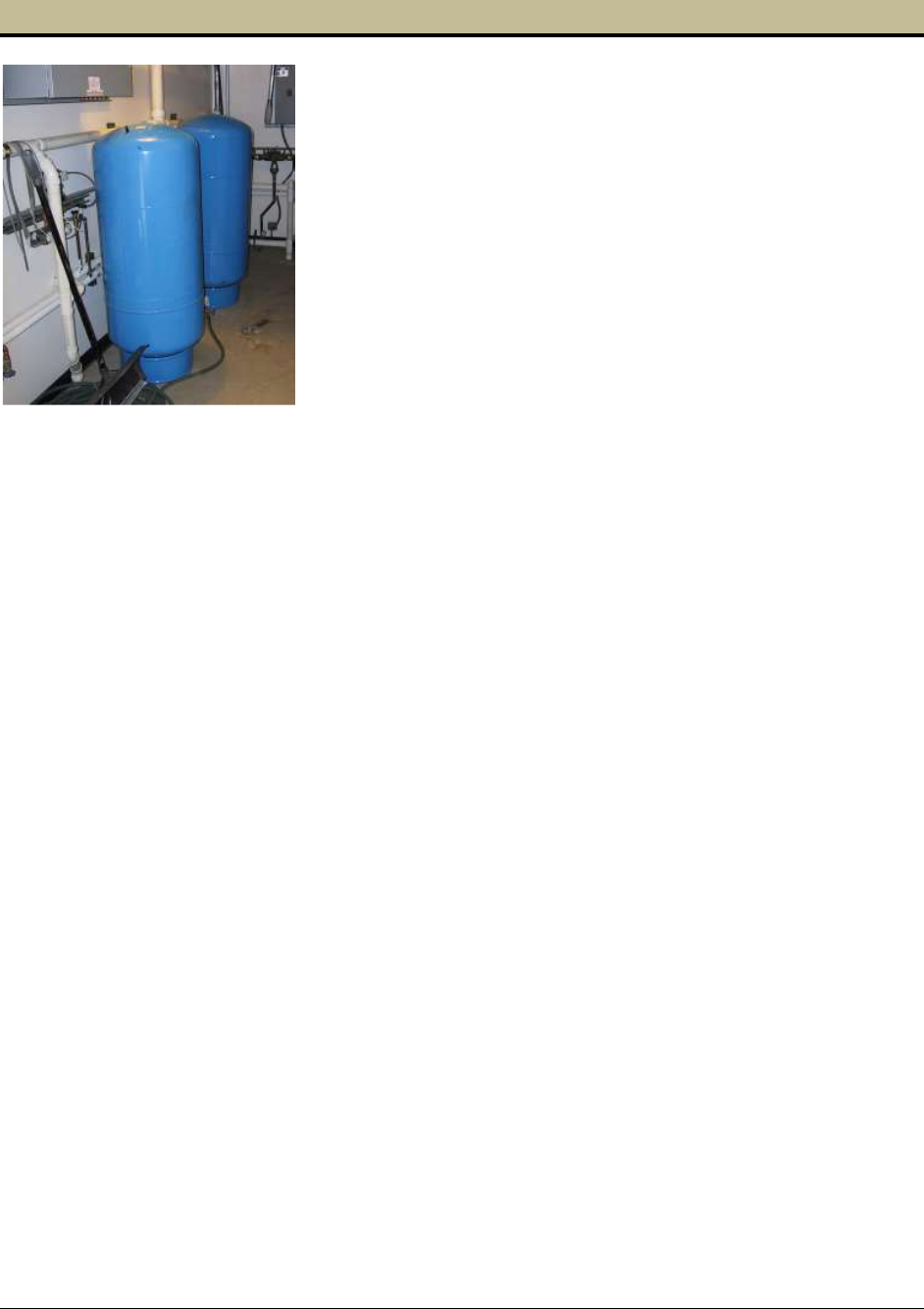
Group B Water System Design Guidelines (DOH 331-467) Page 34
September 2018
CHAPTER 5 Well Pump, Bladder Tanks, and Pump House
Chapter 5 explains how to make well pumps and pressure tanks
work together as a single system capable of reliably providing
safe drinking water to customers of new Group B water
systems.
5.0 Well Pump
Your job is to select a well pump suited to the specific needs of
your proposed water system. It’s not enough to consider the
horsepower rating of the pump motor (such as “I need a 5-hp
pump”). In fact, before you select the pump motor size you must
properly identify the right pump for your well.
5.0.1 Calculate Minimum Well Pump Discharge Rate
Begin your well pump selection process by referencing how much water your well can produce,
as determined by your pump test (Section 4.1.2). If your well can produce up to the PHD
determined for your proposed system (Sections 3.1 and 3.2), we recommend you select your well
pump based on the PHD. A well pump capable of meeting the PHD of the proposed water
system eliminates the need for equalizing storage (Section 5.3.1). If there is no requirement to
provide fire suppression, then a well and well pump capable of supplying the PHD enables you
to design your Group B water system using only one pump (the well pump) and pressurized
storage (Section 5.1). This is the simplest, least expensive design option.
If your well cannot produce at least the PHD, then your design will have to include additional
equipment, including an atmospheric storage tank and possibly a booster pump. This equipment
will add considerably to the cost of constructing your water system. In this instance, selecting a
well pump that takes maximum advantage of the well capacity will minimize the size of your
atmospheric storage tank.
5.0.2 Calculate Minimum Required Well-Pump Discharge Pressure
After you determine the well-pump discharge rate, you have to determine the pressure that the
well pump must generate at the selected discharge flow rate. When you know the pump
discharge rate and the pressure the pump must generate, you can begin the process of selecting
the appropriate well pump.
There are two well-pump design scenarios.
1. A simple system consists of only a well pump and bladder tanks; the well pump is the
only pump in the system. The well pump must generate enough flow and pressure to
supply at least the PHD, and to provide at least 30 psi during PHD conditions along
property lines adjacent to distribution mains and at the point of service to each customer
connected to the distribution system (WAC 246-291-200 (4)).

Group B Water System Design Guidelines (DOH 331-467) Page 35
September 2018
2. A complex system consists of a well pump and an atmospheric storage tank. The well
pump must generate enough pressure to lift the water to fill the atmospheric tank. In some
designs, the storage tank is next to or near the well, and the system will include a booster
pump to move the water from the storage tank to the distribution system. In others, the
storage tank will be on top of a hill or elevated sufficiently high above the service area so
that the reservoir provides adequate pressure to serve customers without a booster pump.
The pressure the well pump must generate sometimes is measured in “feet,” as in “feet of head.”
Water at a depth of 2.31 feet creates exactly 1 psi of pressure. In other words, if you had a
pressure gauge connected to the bottom of a water tank, and the gauge read 30 psi, you’d know
that there is 69 feet of water standing inside the water tank (30 x 2.31 = 69). Some well pump
manufacturers refer to a pump’s discharge capacity in gpm and “feet,” rather than gpm and psi.
Just remember that “feet” and “psi” are interchangeable terms.
The following describes the design considerations for a simple system consisting of a well pump
capable of delivering the PHD and one or more pressure tanks. This is the most common design
scenario.
Total Dynamic Head
The total dynamic head of a pump is the sum of the total static head, the pressure head, and the
friction head. We explain these terms below.
Static Head
The total SH is the difference in elevation between the water surface in the well while the well
pump is running (not the elevation of the pump itself) and your customers. This is a major factor
in determining the pressure your well pump must generate, so be sure to base it on accurate
measurements. To calculate the difference in elevation, you must know both:
• The elevation of the top of your well casing and the elevation of the water surface in the
well at the selected well pump discharge rate (this distance is measured during the pump
test).
• The elevation of the top of your well casing and the ground surface elevation along the
planned distribution system piping to your customers.
Pressure Head
Public water systems must provide at least 30 psi during PHD conditions along property lines
adjacent to distribution mains and at the point of service to each customer connected to the
distribution system (WAC 246-291-200 (4)). You can convert the pressure head at any point
along the distribution pipeline from pressure (psi) to pressure head (feet) by multiplying the
pressure by 2.31. For example, 30 psi is equal to 30 x 2.31 = 69 feet of head. This means that the
minimum allowable value for the pressure head is 69 feet.
Equation 5-1: TDH = SH + FH + PH
Where:
TDH
=
Total Dynamic Head, measured in feet
SH
=
Static Head, measured in feet
FH
=
Friction Head, measured in feet
PH
=
Pressure Head, measured in feet
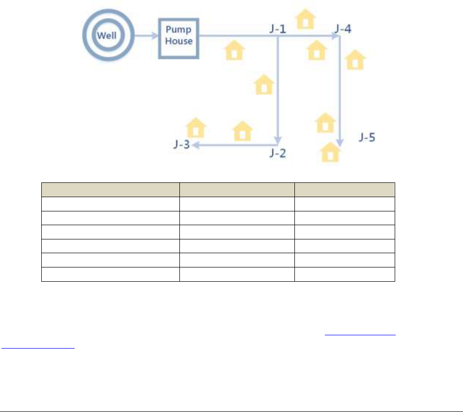
Group B Water System Design Guidelines (DOH 331-467) Page 36
September 2018
Friction Head
Your well pump moves water up the discharge pipe in the well, through all the pipes and valves
in your pump house, and then out into the distribution system to your customers. While on this
journey, the water is constantly losing energy due to friction of the water flowing inside the
pipes, fittings, and valves. This energy loss may be described as the loss of “feet,” as in “at 50
gpm, water flowing through a two-inch Schedule 40 PVC pipe results in 4.2 feet of head loss per
100 feet of pipe.” The 4.2 feet of head loss is equal to about 2 psi.
The friction head for a piping system is the sum of all the friction losses from the well to the end-
user. Friction loss occurs through valves, meters, and fittings in greater proportion than through
an equal length of pipe. To accommodate these added sources of friction loss, Worksheet 5-1
provides an allowance of 10 feet of friction loss (4 psi) for these common well-house features.
Use the information from Table 5.1 and 5.2 to complete Worksheet 5-1. Estimating friction head
loss in the piping system requires estimating the flow through each pipe segment. We
recommend using the values in Table 3.2 and 3.3 and assigning water demand at the end of each
pipe segment equal to the number of houses or nonresidential uses within and downstream of the
end of the pipe segment. See the diagram and table below for an example.
Pipe Segment
Homes downstream
Flow (gpm)
Well to Pump House
9
50
Pump House to J-1
9
50
J-1 to J-2
3
29
J-2 to J-3
2
24
J-1 to J-4
5
37
J-4 to J-5
3
29
Alternatively, you can use a computer-based hydraulic model to identify the total dynamic head
required to maintain the minimum pressures throughout the distribution system. EPANET,
distribution system hydraulic modeling software, is available free at epa.gov/water-
research/epanet. There are also other, more sophisticated hydraulic modeling software tools
available for purchase.
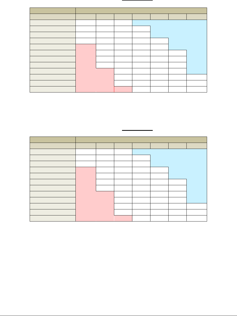
Group B Water System Design Guidelines (DOH 331-467) Page 37
September 2018
Table 5.1
Head loss, ft/100 ft of pipe
For PVC Pipe Schedule 40
Pipe Size (inches)
Flow rate, gpm
1
1 ¼
1 ½
2
2 ½
3
4
5
1.7
0.4
0.2
10
6.0
1.6
0.7
0.2
15
12.8
3.3
1.5
0.5
20
21.8
5.6
2.6
0.8
0.3
25
8.5
4.0
1.2
0.5
30
11.9
5.5
1.6
0.7
0.2
35
15.8
7.4
2.2
0.9
0.3
40
20.2
9.4
2.8
1.2
0.4
45
11.7
3.4
1.4
0.5
50
14.3
4.2
1.8
0.6
0.2
60
20.0
5.8
2.5
0.9
0.2
70
7.8
3.3
1.1
0.3
Table 5.2
Head loss, ft/100 ft of pipe
For PVC Pipe Schedule 80
Pipe Size (inches)
Flow rate, gpm
1
1 ¼
1 ½
2
2 ½
3
4
5
2.6
0.7
0.3
10
9.6
2.3
1.0
0.3
15
20.4
4.9
2.2
0.6
20
8.3
3.8
1.1
0.4
25
12.6
5.7
1.6
0.7
30
17.6
8.0
2.3
0.9
0.3
35
23.4
10.6
3.0
1.3
0.4
40
13.6
3.8
1.6
0.5
45
16.9
4.8
2.0
0.7
50
20.5
5.8
2.4
0.8
0.2
60
28.7
8.1
3.4
1.1
0.3
70
10.8
4.5
1.5
0.4
Not
meaningful
Not
recommended
Not
meaningful
Not
recommended

Group B Water System Design Guidelines (DOH 331-467) Page 38
September 2018
Worksheet 5-1 (included with Group B Workbook)
Total Dynamic Head Calculation
Friction Head Calculation
Static Head Calculation,
Assume top of well casing
elevation is 0 ft.
Min.
Pressure
Head, ft
Min.
Total
Dynamic
Head, ft
Pipe
Segment
From
To
Pump
or Flow
Rate,
gpm
Pipe
Size,
inches
Friction
Loss per
100 ft
Pipeline
Length,
ft
Pipe
Segment
Friction
Loss, ft
Top of well
casing to
water while
pumping, ft
Ground
Elev. at
“to”
Elevation
difference,
ft
1
Well pump
Top of
well casing
69
2
Top of well
casing
69
3
69
4
69
5
69
6
69
7
69
8
69
9
69
With a simple system consisting of only a well pump and bladder tanks, the well pump is the only pump in the system. Without a storage tank,
the well pump must generate enough flow and pressure to supply at least the PHD, and to provide at least 30 psi during PHD conditions along
property lines adjacent to distribution mains and at the point of service to each customer connected to the distribution system.
For the segment that includes the well house, add 10 feet of friction loss to account for losses related to fittings and valves. If you intend to use a
cycle control valve, add additional friction loss per manufacturer’s data (Section 5.0.6)
Total up the “pipe segment friction loss” for each pipe segment + “elevation difference” + “minimum pressure head” values. The highest Total
Dynamic Head (TDH) is the minimum pressure, expressed in “feet of head” that the well pump must generate while pumping the peak hourly
demand. You may wish to select a pump with a TDH greater than the required minimum.
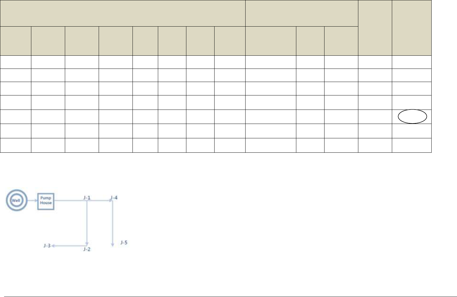
Group B Water System Design Guidelines (DOH 331-467) Page 39
September 2018
Example 5-1
Total Dynamic Head
Friction Head Calculation
Static Head Calculation,
Assume top of well casing
elevation is 0 ft.
Min.
Pressure
Head, ft
Min. Total
Dynamic
Head, ft
Pipe
Segment
From
To
Pump or
Flow
Rate, gpm
Pipe
Size,
inches
Friction
Loss per
100 ft
Pipeline
Length,
ft
Pipe
Segment
Friction
Loss, ft
Top of well
casing to water
while pumping,
ft
Ground
Elev. at
“to”
Elevation
difference,
ft
1
Well pump
Top of well
casing
50
2
5.8
160
9.3
119.3
0
119.3
69
197.6
2
Top of well
casing
Exit pump
house
50
2
5.8
75
4.3 +10
=
14.3
119.3
0
119.3
69
211.9
3
Exit pump
house
Junction #1
50
3
0.8
400
3.2
119.3
20
139.3
69
235.1
4
Junction #1
Junction #2
29
2
2.3
300
6.9
119.3
30
149.3
69
252.0
5
Junction #2
Junction #3
24
2
1.6
250
4.1
119.3
50
169.3
69
6
Junction #1
Junction #4
37
2
3.0
500
15
119.3
30
149.3
69
260.1
7
Junction #4
Junction #5
29
2
2.3
500
11.5
119.3
10
129.3
69
251.6
Objective: Determine minimum TDH required at the end of each pipe segment. Choose the highest TDH value.
Conclusion: The well pump must be capable of producing at least 276 feet of TDH at 50 gpm. See below.
Pump lift from water level in the well to the top of the well casing = 119.3 ft
Elevation change (increase) from top of well casing to Junction #3 = 50 ft
Total Static Head (SH) from well pump to Junction #3 = 169.3 ft
Total Friction Head (FH) between well pump and Junction #3 = 9.3 + 14.3 + 3.2 + 6.9 + 4.1 = 37.8 ft
Total (minimum) Pressure Head (PH) required at Junction #3 = 69 ft (provides 30 psi at the customer)
Eq. 5-1: TDH = SH + FH + PH
TDH = 169.3 + 37.8 + 69 = 276.1 ft (equal to 119 psi at the pump itself) at 50 gpm
276.
1

Group B Water System Design Guidelines (DOH 331-467) Page 40
September 2018
5.0.3 Well Pump Selection and Controls with Pressure Tanks
With bladder tanks and no storage tank, a pressure switch located in the pump house, near the
bladder tank(s), will control the well pump. The “pump-on” pressure must be set so that the
pressure is at least 30 psi during PHD conditions along property lines adjacent to distribution
mains and at the point of service to each customer connected to the distribution system, just
before the well pump comes on to recharge the pressure tanks (WAC 246-291-200 (4)).
Continuing with our Example 5-1, to maintain 30 psi at Junction #3 with the well pump off, the
pressure in the well house must be 276.1 ft – 119.3 ft – 9.3 ft – 14.3 ft = 133.2 ft = 57 psi. In our
example, this is the pressure at which the well pump must come on (“pump-on” setting) to
maintain a minimum of 30 psi everywhere in the distribution system.
The pump-off setting should be about 20 psi greater than the pump-on setting. In this example,
80 psi as the pump-off setting would work fine. In our example, this corresponds to a “pump
head” of:
80 psi x 2.31 = 185 feet (pressure head inside the pump house) + 119.3 (vertical distance
from top of well casing to water level in the well) + 9.3 + 14.3 = 327.9 feet TDH (use 330
ft).
In this example, the pressure in the distribution system will not exceed 80 psi or fall below 30 psi
between the “pump on” and “pump off.”
5.0.4 Well Pump Selection and Control with a Storage Tank
The principles above also apply to determining the TDH of the well pump when pumping to a
storage tank. Here are the major differences: When applying equation 5-1, the Pressure Head
(PH) is zero because the storage tank is open to the atmosphere (unpressurized storage); and the
Static Head (SH) must include the difference in elevation between the water level in the well and
the water level in the reservoir.
You may need to include a reservoir in your Group B water system design for many reasons. For
example:
• The well and well pump cannot produce enough water to satisfy the peak hour
demand. Water stored in a reservoir can provide the supplemental supply needed
to serve the distribution system.
• The owner of the water system seeks the higher level of service reliability that a
reservoir offers.
• The water system must be capable of providing fire protection.
A reservoir design may supply water to the distribution system directly or by gravity. Gravity
uses the elevation difference between the water in the reservoir and customers. This difference in
elevation must provide at least 30 psi during PHD conditions along property lines adjacent to
distribution mains and at the point of service to each customer connected to the distribution
system (WAC 246-291-200 (4)). Alternately, you may design a reservoir without sufficient
difference in elevation between water in the reservoir and customers if the water is re-pumped
from the reservoir into the distribution system so that the 30 psi standard is met.

Group B Water System Design Guidelines (DOH 331-467) Page 41
September 2018
The well may pump to a reservoir directly through a dedicated water main from well to reservoir
or indirectly through the distribution system (where the pipe between the well pump and
reservoir also serves customers). In either case, the level of the reservoir must control the well-
pump function. The operating range between the “well pump off” and “well pump on” defines
the “operating storage” volume in your reservoir (Section 7.0). Float switches in the reservoir
usually control these two levels by sending a signal to the well-pump controller through direct
wire or wireless (radio frequency) communication.
The basis of the well pump control system design is the reservoir volume between “pump on”
and “pump off,” and the well pump discharge. The reservoir design should provide the volume
required to prevent excessive cycling (starting and stopping) of the pump motor. Unless the well-
pump motor manufacturer specifically allows starts more frequently, the pump should not be
called to fill the reservoir more than six times in an hour.
To simplify the well pump control system design, set the well “pump on” and “pump off” levels
in the reservoir so that the volumetric difference between these two levels is equal to 10 times
the discharge rate of the well pump. For example:
Suppose the water system design presented in Example 5-1 has a 3,500-gallon
polyethylene tank that’s eight feet in diameter and 10 feet tall. The well pump
produces 50 gpm, and pumps directly to the reservoir. No pressure tanks are
connected to the well pump discharge. The reservoir is right outside the well
house, and the base of the tank is at the same elevation as the wellhead.
The TDH the well pump must pump against is equal to (see Example 5-1):
• The pipe segment friction loss for pipe segments 1 and 2 (9.3 ft
+ 14.3 ft = 23.6 ft)
• From the top of well casing down to the stabilized water level in
the well while the pump is on (119.3 ft)
• From the top of the well casing to top of the 3,500-gallon tank
(10 ft)
• TDH the well pump must overcome to produce 50 gpm is 23.6
+ 119.3 + 10 = 152.9 ft.
The water in the reservoir will have to be re-pumped into the distribution system
to provide at least 30 psi throughout the distribution system during peak hour
demand (see Chapter 8 for booster pump design).
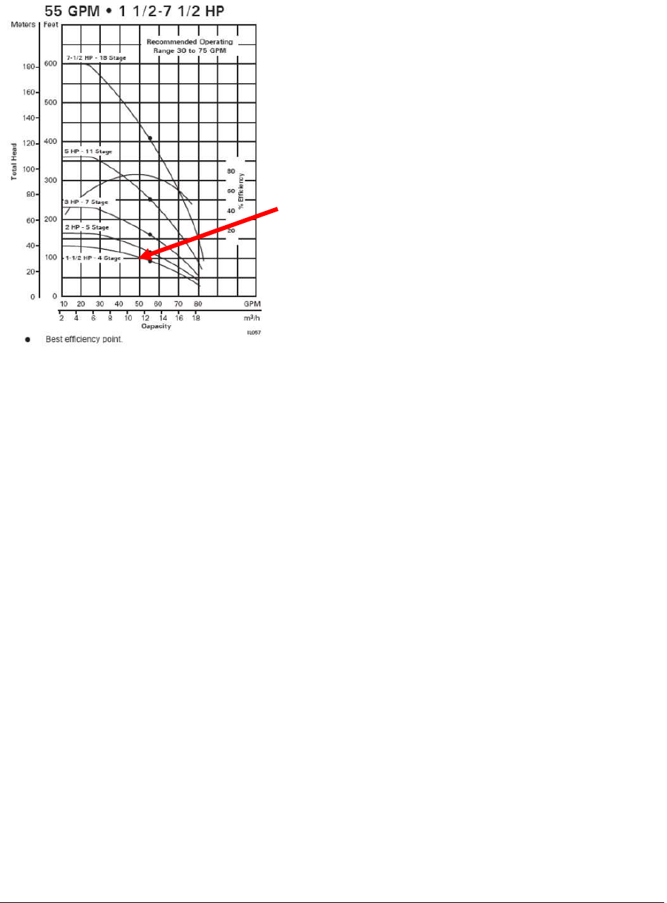
Group B Water System Design Guidelines (DOH 331-467) Page 42
September 2018
5.0.5 Well Pump Selection
In this section, we will use the example water system introduced in Example 5-1 above.
In our example, we are looking for a pump that can produce 50 gpm while generating at least
276 ft TDH. In the set of pump curves below, the 5 hp pump can produce 50 gpm at about 275-
280 ft TDH (see C below). This same pump will produce about 35 gpm at 330 ft TDH (see A
below). The operating pumping range for the 5 hp pump will be between 35 gpm (the “pump
off” setting) and 50 gpm (the “pump on” setting - see B and D).
The figure at left is a family of pump curves,
beginning with a 7½ hp pump (top) down to a 1½ hp
pump (bottom).
A pump curve expresses the relationship between
discharge pressure (“total head” or TDH) shown on
the vertical axis, and discharge pumping capacity
(gpm) shown on the horizontal axis.
For example, look at the 1½ hp pump curve. It shows
this particular pump is capable of producing 50 gpm
at 100 ft TDH.
The rising and falling curve in the middle of graph is
the pump efficiency curve. As you can see, this family
of pumps is most efficient between 35-60 gpm.
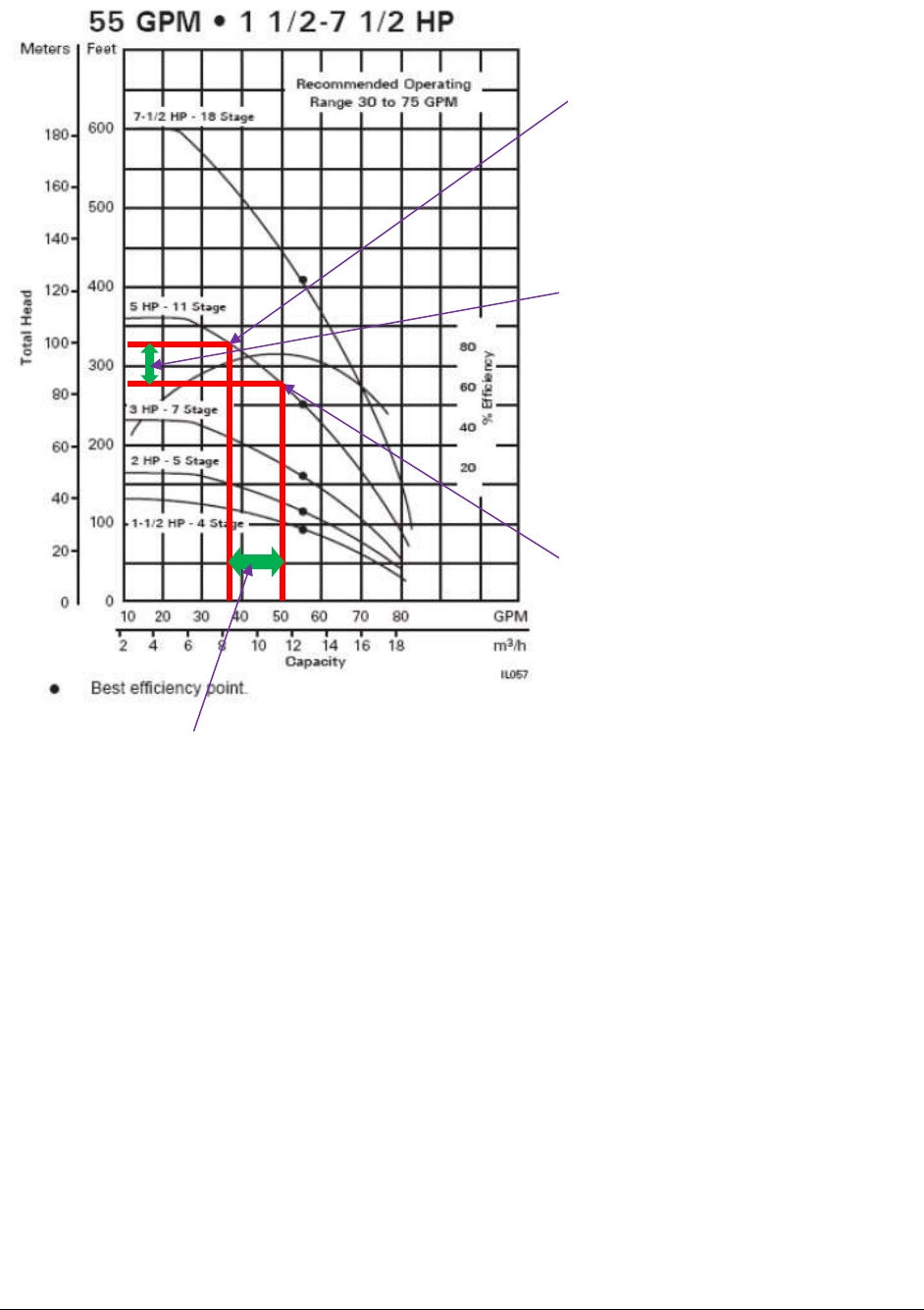
Group B Water System Design Guidelines (DOH 331-467) Page 43
September 2018
5.1 Pressure Tanks
Water systems use pressure tanks with well pumps and when re-pumping water, such as from a
reservoir into a distribution system. Pressure tanks make it possible to deliver water within a
selected pressure range without continuously operating pumps or having the pumps start every
time there is a minor demand for water.
Two types of pressure tanks are used to protect water system pumps. Each has its own basic
design procedures. Conventional tanks, also called hydropneumatic tanks, allow air-water
contact. Bladder tanks have a membrane separating the air from the water.
5.1.1 Hydropneumatic Tanks
Designers use hydropneumatic tanks in well pump installations that are usually larger than
necessary for Group B water systems. If you intend to design a hydropneumatic tank system,
please see our Water System Design Manual (331-123) online at
doh.wa.gov/portals/1/Documents/pubs/331-123.pdf.
C. This 5 hp pump will generate
50 gpm at 276 ft TDH. This is
the minimum TDH required in
the example above, and
represents the “pump-on” set
point for the pressure switch in
the pump house.
A. This 5 hp pump will generate
about 35 gpm at 330 ft TDH.
This is the “pump off” set
point for the pressure switch
in the pump house in the
example above.
B. In our example, the pressure
switch will be set so that the
operating range of the 5 hp
well pump will be between 276
ft TDH and 330 ft TDH. This
operating range for the well
pump should provide a
minimum of 30 psi at Junction
#3. (see Section 5.1.3)
D. In our example, the well pump will operate
between 35 gpm (when the pump shuts off) and
50 gpm (the moment the pump is turned on).

Group B Water System Design Guidelines (DOH 331-467) Page 44
September 2018
5.1.2 Bladder Tanks
Bladder tank sizing depends on the number of “selected-size” tanks needed to provide pump
protection. Bladder tanks have pre-charged air bladders with a pressure of two psi below the low
operating (pump-on) pressure for the system. Engineers should call out this stipulation in the
design specifications.
For more information, see Troubleshooting Bladder Pressure Tanks (331-342) online at
doh.wa.gov/portals/1/Documents/pubs/331-342.pdf.
5.1.2.1 Bladder Tank Sizing Equation
Equation 5-2: T
s
>
(R)(Q
p
)
(N
c
)(V
B
)
Where:
R
=
15(P
1
+ 14.7)(P
2
+ 14.7) (or refer to Table 5.3)
(P
1
- P
2
)(P
2
+ 9.7)
V
B
=
The gross volume of an individual bladder tank in gallons, or bladder tank size
(“86-gallon tank,” for example).
T
s
=
The number of bladder tanks of gross volume V
B
P
1,
P
2
=
Pressures selected for water system operation in psig (gauge pressures). P
1
corresponds to the pump-off pressure and P
2
to the pump-on pressure
Nc
=
Number of pump operating cycles per hour. This should be the maximum number
of pump motor starts per hour as justified and documented by the pump or motor
manufacturers' warranty. Without such information, this should be no more than
six cycles per hour.
Q
p
=
Pump delivery capacity in gallons per minute at a midpoint of the selected
pressure range. Determine this by examining pump curves or tables. If this value is
not used, the designer must use the Q
p
that occurs at P
2
(pump-on).
5.1.2.2 Bladder Tank Design Procedure
1. Based on water system hydraulic requirements, select the operating range of pressure, P
1
(pump-off) and P
2
(pump-on). P
2
pressure must satisfy minimum system pressure
requirements (WAC 246-291-200(4)).
2. Select the operating cycles per hour, N
c
. The value for N
c
should not exceed six cycles
per hour unless documented manufacturers’ warranties justify larger values. For multiple
pump installations, N
c
may be increased if an automatic pump switchover system is
installed to automatically alternate pumps. The actual increase in N
c
should be justified
by documented manufacturers’ warranties.
3. Determine the delivery capacity, Q
p
, for the midpoint of the operating pressure range
[(P
1
+ P
2
)/2]. The pump capacity must meet system requirements at P
2
pressure (see
WAC 246-291-200 (4)).

Group B Water System Design Guidelines (DOH 331-467) Page 45
September 2018
4. Select an appropriate gross volume, V
B
, for each bladder tank (bladder tank size). This
volume should be available from bladder tank manufacturers. Do not select bladder tank
sizes larger than 120 gallons gross volume.
5. Calculate the value of R. For convenience, Table 5.3 gives R-values for several
commonly used pressure ranges.
6. Use Equation 5-2 (see above).
7. Round up the value determined in Step 6 to the nearest whole number. This is the number
of tanks, each with the selected volume, V
B
, to be used for pump protection.
Table 5.3
R Values for Various Pressure Tank Ranges
P
1
pump-off pressure (gauge)
P
2
pump-on
pressure
(gauge)
55 psi
60 psi
65 psi
70 psi
80 psi
35 psi
58.1
49.8
44.3
40 psi
76.7
61.7
52.6
46.6
45 psi
81.5
65.2
55.5
50 psi
86.4
68.8
51.3
60 psi
76.1
Example 5-2
For a mid-pressure range pumping rate, Q
p
, of 40 gpm, a selected cycling of six cycles per hour,
a bladder tank gross volume of 86 gallons, and a selected pressure range of 60/80, the number of
86-gallon tanks required is determined as follows:
Q
p
= 40; N = 6; V
B
= 86
Using Table 5.3 for P
2
/P
1
= 60/80, R = 76.1
Using Equation 5-2:
T
s
>
(R)(Q
p
)
(N
c
)(V
B
)
T
s
>
(76.1)(40)
= 5.9
(6)(86)
Select six 86-gallon bladder tanks for pump protection, pre-charged to 58 psi (two psi below
pump-on pressure).

Group B Water System Design Guidelines (DOH 331-467) Page 46
September 2018
5.1.3 Reduced Pressure Tank Sizing
Designs using Variable Frequency Drive (VFD) pumping systems or pump cycle control valves
(CCV) will reduce the pressurized storage needed to protect pumps from over-cycling while
maintaining adequate pressure in the distribution system. The criteria used to size pressure tanks
serving a closed pumping system employing a VFD or CCV differs from the approach described
above.
CCVs and VFDs deliver water within controlled pressure ranges at flow rates much less than that
required under a standard design approach (see Sections 5.1.2.1 through 5.1.2.2). Therefore,
water systems using them can have smaller and fewer pressure tanks than those using a single-
speed pump delivering the same maximum flow, controlled by an on-off pressure switch.
Cycle Control Valves. CCVs may be used to control the pressure in a distribution system. A
CCV is intended to extend run time with minimal pressurized storage. It will maintain constant
downstream pressure (the valve’s set point) until demand downstream of the valve falls below
the valve’s prescribed low-flow level. At that point, the pressure will rise to the pressure switch
pump-off set point. A mechanism in the valve prevents it the valve from restricting flow past its
preset minimum.
Depending on the model used, the control valve will stop pump operation at a pre-set threshold
flow of as little as 1 gpm or 2 gpm. At flows higher than this threshold, the valve will open or
close in response to water system demands while the pump operates continuously. Design
engineers who choose to use a CCV should include the head loss through the valve when
determining the friction loss within the pump house, and ensure that the valve is listed under
NSF 61.
As described more fully in Appendix G, the CCV is designed to keep the pump operating nearly
all the time. For most water systems water demand will be very low during nighttime hours,
resulting in prolonged pump operation at the upper end of its pump curve. That is a point of low
pump efficiency, and may cause early failure of the pump if the manufacturer did not design the
pump and motor for prolonged operation at that point on the pump curve. We recommend design
engineers consult directly with the pump vendor or manufacturer to make sure the pump and
motor are compatible with the intended operating conditions.
Variable Frequency Drives. As described more fully in Appendix H, a VFD is an electronic
controller that adjusts the pump motor speed by modulating frequency and voltage. VFDs match
motor speed and therefore pump output to specific water demand through a pressure control
feedback loop to the variable frequency controller.
5.1.4 Labor and Industries Standards for Pressure Tanks
RCW 70.79.080 (5) requires pressure vessels, including bladder tanks greater than 37.5 gallons
in gross volume, to be constructed according to ASME standards (RCW 70.79.080 (5)). The
ASME standard is intended to promote a safe environment and protect against property damage,
injury and death caused by an abrupt tank failure.

Group B Water System Design Guidelines (DOH 331-467) Page 47
September 2018
General Agreement
In 2011, Washington State Department of Labor and Industries (L&I) added an exemption for
non-ASME bladder tanks used in public water systems to a list of proposed changes to RCW
70.79.080. When legislation conflicts with practices that meet the intent of the rule (in this case,
safe operation of bladder tanks used in public water systems), L&I can enter into a general
agreement with another agency until the legislation is changed. Design engineers are responsible
for addressing all applicable L&I requirements at the time of pressure tank design. Refer to
current L&I rules and legislation.
A General Agreement between L&I and ODW requires that design of non-ASME bladder tank
systems conform to the standards shown in Pressure Relief Valves on Pressure Tanks (331-429).
The General Agreement does not apply to hydropneumatic tanks. All hydropneumatic tanks
must be constructed according to the latest ASME specification code (RCW 70.79.080),
regardless of size.
All pressure tanks greater than 37.5 gallons gross volume must have a properly sized and
installed ASME Section VIII pressure relief valve (PRV) (WAC 296-104-316). Pressure tanks
smaller than 37.5 gallons gross volume must have a properly sized and installed pressure relief
device manufactured according to a recognized national standard, the specifications and
certification of which must be provided. We strongly recommend using an ASME Section VIII
PRV for pressure tanks smaller than 37.5 gallons gross volume. PRVs protect a pressure vessel
from over-pressurization due to a failure in the pump control system, intense or over-heating of
the water (during a fire), and pressure surge.
No valves may be between the PRV and the pressure tank. For other design requirements and
guidance, see Pressure Relief Valves on Pressure Tanks (DOH 331-429).
The maximum allowable working pressure for a tank is on the nameplate attached to the tank.
For nonstandard pressure vessels, engineers can determine the maximum allowable working
pressure with the L&I formula in WAC 296-104-405. A properly sized ASME PRV should have
a relieving capacity sufficient to prevent pressure in the vessel from rising more than 10 percent
or 3 psi above the maximum design set pressure of the PRV, whichever is greater.
5.1.5 Locating Pressure Tanks
Pressure tanks should be located above normal ground surface and be completely housed. Buried
pressure tanks are subject to floatation by high groundwater, and allow external corrosion to go
undetected. L&I standards require at least 18 inches of clearance around the tanks for proper
inspection, maintenance, and repair access (WAC 296-104-260). In some cases, it may not be
practical to provide this much clearance all the way around a pressure tank. Therefore, L&I
developed a Boiler/Pressure Vessel Clearance Variance Request form (F620-041-000). It is on
the L&I Boiler/Pressure Vessel website: (lni.wa.gov/forms/pdf/F620-041-000.pdf).

Group B Water System Design Guidelines (DOH 331-467) Page 48
September 2018
5.2 Pump House Design and Construction Recommendations
The pump house design and construction should allow convenient, safe access for removal and
service of equipment. When you construct your Group B well house, be sure to:
• Install a wall-mounted thermostat-controlled wall heater.
• Use PVC Schedule 80, galvanized iron, or copper piping for all internal piping.
• Support all internal piping properly.
• Install unions and isolation valves at pressure tanks, booster pumps, and other
equipment to allow for equipment removal.
• Secure any booster pump to the floor.
• Install ASME pressure relief valve(s) properly sized based on flow.
• Install a totalizing source meter inside the pump house.
• Install all pressure tanks on the floor.
• Install the raw water tap at least 6-inches above the floor.
• Position pressure gauges so they are easily readable.
• Be sure to install a keyed lock on door.
5.3 Well and Pump House Detailed Drawings and Specifications
The design submittal must include drawings of each project component, including location,
orientation, and size (WAC 246-291-120 (2)). The drawing(s) and specifications of the well
pump, pressure tank(s), and pump house appurtenances should include:
a. Pump-house building specifications.
b. A plan view with a scale of not more than 10 feet to the inch. It must show the
location of the well and proposed pump house, water mains, fittings, valves,
construction and maintenance easements, sanitary control area, existing above ground
and underground utilities (gas, electric, power, sewer, irrigation, and so forth), and
other natural or man-made features important to the proper construction of the pump
house.
c. Location, size, capacity, and construction materials of all pipes, pumps, valves,
sample tap, water meter, pressure gauges, pressure switch, pressure tanks, pressure
relief valves, and other key components inside the pump house.
d. Manufacturer’s catalog information on the specific well pump showing operating
pump-on and pump-off limits.
e. Manufacturer’s catalog information on the specific bladder tanks and pressure switch.
f. Settings for the pressure switch, pressure relief valves, CCV (if any).
g. Elevation of the top of the well casing above the ground or pump house floor, and
whether the wellhead is located in the 100-year flood plain.
h. Disinfection procedures for well-after-pump installation.

Group B Water System Design Guidelines (DOH 331-467) Page 49
September 2018
i. Disinfection and pressure testing procedures for all well and pump house piping and
tanks.
j. Physical protection of the wellhead (if located outside the pump house).
k. Location of required generator disconnect switch (WAC 246-291-200(11)).
l. Specification for well casing cap, well pitless adaptor, or pitless unit.
m. Typical details of thrust blocking or restraints for internal and below-building piping.
n. All other buried utilities, including storm and sanitary sewers, dry wells, telephone,
natural gas, power and TV cable lines in the project area (existing or proposed
concurrent with pipeline construction) to the extent possible, given existing available
records. Construction details should note that all buried utilities are to be field located
prior to construction.
You must show the following accessories on the drawings:
• Generator disconnect switch (WAC 246-291-200 (11)).
• Source water meter (WAC 246-291-200 (9)).
• Source sample tap (WAC 246-291-200 (9)).
• Each pressure tank equipped with an isolation valve and an ASME pressure relief
valve (WAC 296-104-316).
• A lock on the pump house door (WAC 246-291-140 (1)).
References
WSDOH, 2009. Water System Design Manual (331-123), Washington State Department of
Health, Olympia, Washington.

Group B Water System Design Guidelines (DOH 331-467) Page 50
September 2018
CHAPTER 6 Piping Design and Construction
Chapter 6 explains how to design and construct the distribution system so that it can deliver a
safe and reliable water supply from the well to the system’s customers. This guidance, combined
with the information on friction loss and distribution system design from Chapter 5, assumes
your proposed water system will not provide fire suppression (fire flow).
If you intend to design a water system capable of providing fire flow, a professional engineer
licensed in Washington State must prepare and submit the water system design (WAC 246-291-
120(4)). For further guidance, see our Water System Design Manual (331-123).
6.0 Piping Material
When designing a water main, it is important to consider the type of pipe and the pressure needs
of the system. Excessive system pressure can increase the risk of pipe failure and cause
customers to wastewater. Distribution system pressure should not exceed 100 psi. All
distribution piping should be rated to withstand the maximum pressure they may experience
during operations and pressure testing.
PVC pipe is the most common pipe material used in small water systems. Other pipe material
includes ductile iron, steel, High-Density Polyethylene (HDPE), and cross-linked polyethylene,
abbreviated PEX or XLPE. The use of asbestos-cement, cast iron, or galvanized iron pipe in
distribution system design is not recommended. In addition, the use of irrigation pipe, drainpipe,
or other thin-walled pipe material is strictly prohibited for potable water systems. The designer
or design engineer must use established standards, such as AWWA or ASTM, when justifying
the material and class of pipe and pipefittings selected (WAC 246-291-200(1)).
PVC pipe “schedule” refers to a specific ratio of the outside diameter of the pipe and the pipe
wall thickness, known as the Dimensional Ratio (DR). PVC pipe “class” reflects the working
pressure rating of the pipe. For example, PVC Schedule 80 pipe (DR 11) has a greater pressure
rating than PVC Schedule 40 pipe (DR 16) because of a thicker pipe wall. Because both pipe
schedules have the same Outside Diameter (“OD”), the Schedule 80 pipe (with the thicker pipe
wall) has a smaller Inside Diameter (“ID”). The head loss difference between Tables 5.1 and 5.2
reflect the difference in the pipes’ inside diameter. You should use flow rate, pressure, and
allowable head loss as the basis for selecting a pipeline size and schedule.
We recommend using a minimum 1½-inch diameter and maximum DR 21 pipe in all
distribution main designs. The recommended minimum size provides for conveyance without
undue friction loss. Larger pipe sizes may be needed. The recommended maximum DR (measure
of wall thickness) provides an allowance for hydrostatic testing pressure (Section 6.4), less than
perfect installation (depth of bury, bedding, joints, expansion and contraction), unusual pressure
conditions (surge pressures, poorly controlled leak testing), and a general design factor of safety.
Applying a maximum DR 21 excludes ASTM D2241 PVC Class 160 and AWWA C900 Class
100 pipe.
Any specified and installed pipe and pipe fittings must conform to material standards for contact
with potable water, ANSI/NSF Standard 61 (WAC 246-291-205).

Group B Water System Design Guidelines (DOH 331-467) Page 51
September 2018
6.1 Pipe Burial, Bedding, and Thrust Blocks
Pipelines must be installed below the frost line and “bedded” with uniform material that doesn’t
present a risk to the pipe. PVC pipe is brittle and has little resistance to the forces of a sharp or
heavy rock pressing on it or its fittings. Poor bedding material, and failure to compact the
bedding material around the pipe, may result in pipeline failure. You should place, spread, and
compact bedding at a minimum of six inches beneath, beside, and over the pipe.
Pipes should be buried below the frost line as determined by the most severe cold weather on
record; otherwise, pipelines should be protected against freezing by some other means
(insulation, heat tracing). When determining proper depth, designers should evaluate temperature
variations in the area, especially at high altitudes, in Eastern Washington, and beneath regularly
plowed paved surfaces. The minimum fill depth over the top of the pipe should be at least 36
inches, even in temperate areas. The designer may justify another depth (for example, to avoid
underground obstructions or rocky conditions). If providing less than 36 inches of cover, you
should consider the pipe load rating and the location of the installation (to avoid crushing the
pipeline due to traffic loads).
Depending on the pressure and the size of the pipe, a change in pipe direction can cause
substantial forces at pipe fittings such as bends, tees, crosses, and dead-end caps. You should
consider installing thrust blocks to protect the new pipeline from these forces. Thrust blocks are
typically made of concrete poured in place between the fitting and the solid, undisturbed earth
wall of the pipe trench. Restrained joint pipe may be used instead of thrust blocks to prevent pipe
separation due to unequal hydraulic forces at pipe fittings.
6.2 Isolation Valves, Flushing Hydrants, and Air Release Valves
Isolation valves provide a way to isolate sections of the distribution system. Your Group B water
system should have enough valves on water mains to minimize the number of customers without
water service and minimize hazards during repairs. We recommend valves on each branch of
pipeline “tees” and “crosses.”
Pipelines should be flushed from time to time, especially dead-end lines. To flush a pipeline, you
must generate sufficient flow velocity and have an appropriate egress point for the flushed water.
The minimum effective flush velocity is three feet per second. For example, it takes about 18
gpm to generate 3 fps flow velocity in a 1½-inch pipeline, and it takes about 30 gpm to generate
the same flushing velocity in a two-inch diameter pipe. A small flushing device installed at the
end of dead-end lines will facilitate pipeline flushing. To view options for flushing, conduct an
Internet search under “yard hydrants” or “flushing hydrants.”
You may not use yard hydrants that drain the riser into the ground. The weep hole presents a risk
of contamination to the distribution system through a cross connection with contaminated
groundwater. If you choose to use a yard hydrant, the Uniform Plumbing Code requires you to
use a model that does not drain into the ground. Yard hydrants that conform to American Society
of Sanitary Engineers Standard 1057 are acceptable because they do not drain into the ground.

Group B Water System Design Guidelines (DOH 331-467) Page 52
September 2018
You should provide a means to release accumulated air at high points on the distribution system.
You may use an automatic air release valve, but you must install it in a traffic-rated concrete
vault with a daylight drain if the pipe is within a road right of way. This can be very expensive to
construct, and requires periodic inspection and maintenance. The preferred way to vent air is
manually, using a blow-off hydrant or even a service connection at high points. To the extent
possible, slope the profile of the installed water main and locate it to create as few high points as
possible. If accumulated air is not released, it can restrict or even completely block the flow of
water through the pipe.
6.3 Distribution System Pipeline Easements
Distribution system pipelines must be installed in the public right-of-way or within private
property easements. The water system owner must have access to maintain pipelines and all
related components, such as valves, meters, flushing hydrants, and so on. Your design submittal
must show all distribution system components either within the public right-of-way or within a
private property easement. The easement must be wide enough to accommodate all work
(excavation, equipment access, and turning radius). We recommend a width of at least 15-feet
(7.5 feet on each side of the pipeline).
6.4 Pressure and Leakage Test
To check the quality of pipe joints and fittings, it is necessary to conduct a pressure and leakage
test. The test must follow the testing procedures the designer or design engineer specified in the
approved design submittal (WAC 246-291-200(1)). The project engineer or the owner’s
representative should be present during this critical test to verify that it meets the specifications.
Pressure testing standards are in the Standard Specifications for Road, Bridge and Municipal
Construction (WSDOT/APWA 2012), available free on the WSDOT website. These standards
state:
All water mains and appurtenances shall be tested in sections of convenient
length under a hydrostatic pressure equal to 150 psi in excess of that under which
they will operate, or in no case shall the test pressure be less than 200 psi.
6.5 Disinfection
Purveyors must properly disinfect all components of a new or expanding Group B water system
before putting the new or expanded system into service. The disinfection process must meet the
specifications approved for the water system, such as AWWA C651or WSDOT/APWA (2012)
for all sizes of water mains; AWWA C652 for water storage facilities; and AWWA C654 for
well disinfection (WAC 246-291-220(1) and (2)).
6.6 Microbiological Testing
Each of the disinfection standards listed in Section 6.5 includes a requirement for coliform
bacteria testing. Water systems must follow the standards for coliform testing done as part of
disinfecting all the components of a new or expanding Group B system (WAC 246-291-220).
The engineer must attest to satisfying these coliform testing requirements and satisfactory
coliform test results when completing the Construction Completion Report form (WAC 246-291-
120(5)). To ensure the samples properly represent water quality in the water system, purveyors
should take water samples after sufficiently flushing the new lines and equipment.

Group B Water System Design Guidelines (DOH 331-467) Page 53
September 2018
6.7 Separation from Nonpotable Piping Systems
The water system design should provide at least a ten-foot horizontal and 18-inch vertical
separation above nonpotable pipelines (sanitary sewers, reclaimed water piping, irrigation lines,
and so on). The 18-inch vertical separation should be the measured distance between the closest
sides of the two pipes. For additional guidance on potable and nonpotable pipe separation,
consult Pipeline Separation Design and Installation Reference Guide (WSDOE and DOH 2006).
6.8 Service Connections
6.8.1 Service meters and service lines
We recommend that you install the water service line at the same depth and with the same
bedding as the water main. The water service line should be least one-inch in diameter and be
made of PVC, copper, HDPE, or PEX. Using a one-inch service line instead of a ¾-inch service
line decreases friction loss due to flow from the water main to the building by a factor of three.
For many homeowners and businesses, installing a one-inch service line is worthwhile because it
noticeably improves the level of service.
Residential fire sprinkler systems demand higher flow and pressure. Therefore, a residence with
fire sprinklers may require a larger diameter water service line. Consult your local building code
for guidance.
You should install a separate curb or meter “stop” (valve) for each service connection. These
valves allow system managers or the property owner to shut off an individual connection without
interrupting service to other customers. A curb stop is a valve installed at the property line if
there is no meter at the property line. You can operate a curb stop from the surface. A meter stop
is a valve installed just upstream or downstream of the meter.
Service meters are not required, but we recommend every designer include them because they
enable the system manager to proportion the cost of service fairly and reduce the incidence of
over-use at the expense of the other consumers.
6.8.2 Cross-connection control
A cross connection is any actual or potential physical connection between a public water system
or a consumer's water system and any source of nonpotable liquid, solid, or gas that could
contaminate the potable water supply by backflow. Because all Group B water system users
share a common distribution system, contamination from one connection has the potential to
move about the distribution system and contaminate the water supply to other connections.
On certain premises, the contamination hazard associated with the plumbing and water use may
require a cross-connection control assembly. This special valve assembly prevents water from
flowing back into the distribution system. For guidance, see Cross Connection Control for Small
Water Systems (331-234) online at http://doh.wa.gov/odwpubs/.
Many commercial properties involve water uses that pose a threat of a cross connection. You
should consult the local building official to determine what, if any, cross-connection control
assembly is needed on a commercial customer’s service line.

Group B Water System Design Guidelines (DOH 331-467) Page 54
September 2018
Most single-family homes do not pose a high health hazard to the Group B water system users.
There is a potential for problems if single-family homes have access to a separate water supply.
Your development’s Covenants, Conditions, and Restrictions (CC & R) should require proper
cross-connection control assemblies on service connections if your service area is supplied by a
separate irrigation system, or individual homeowners are entitled to drill their own wells.
You must test all cross-connection control assemblies installed on service lines annually to
ensure they continue to function properly. You should include the authority to require such
testing in the development’s CC & R.
6.9 Individual Pressure Reducing Valves
If you anticipate that pressure at any service connection will exceed 80 psi, you are responsible
for recommending that those customers install and maintain individual Pressure Reducing
Valves (PRV) as delineated in the Uniform Plumbing Code (UPC). Water systems should install
individual customer PRV only if they have a written agreement with the customer showing who
is responsible for required PRV maintenance, repair, or replacement. The water system should
check for local ordinances or service agreements on PRV use.
6.10 Distribution System Detail Drawings and Specifications
The workbook must include drawings of each project component, including location,
orientation, and size (WAC 246-291-120 (2)). The drawing(s) and specifications of the
distribution system should include the following.
a. A plan view with a scale of not more than 100 feet to the inch showing the location of
the proposed water mains, fitting, valves, service meters, flushing hydrants,
construction or maintenance easements, existing above-ground and underground
utilities (gas, electric, power, sewer, irrigation), and other natural or man-made
features important to the proper construction of the water main.
b. Location, size, capacity, and construction materials of all proposed pipelines in the
project area. Show all flushing hydrants, valves, meters, air release valves, blow-off
valves, and so on.
c. Identification of lots served under the project scope of work by new distribution
mains serving plats or subdivisions.
d. Typical construction details of all new pipeline tie-ins to existing pipelines.
e. Typical details of pipeline trench cross-section indicating bedding, backfill, and
compaction requirements.
f. Typical details of thrust blocking or other type of pipe restraint.
g. Disinfection and pressure-testing procedures for all new pipelines.
h. Service connection details, where appropriate.
i. All other buried utilities, including storm and sanitary sewers, dry wells, telephone,
natural gas, power and TV cable lines in the project area (existing or proposed
concurrent with pipeline construction) to the extent possible, given existing available
records. Construction documents must clearly state that all buried utilities are to be
field located prior to construction (RCW 19.122).

Group B Water System Design Guidelines (DOH 331-467) Page 55
September 2018
References
WSDOH, 2009. Water System Design Manual (331-123), Washington State Department of
Health, Olympia, WA.
WSDOE, 2008. Criteria for Sewage Work Design. WSDOE Pub. 98-37. Washington State
Department of Ecology, Olympia, WA.
WSDOE and DOH, 2006. Pipeline Separation Design and Installation Reference Guide.
WSDOE Pub. 06-10-029. Washington State Department of Ecology, Olympia, WA.

Group B Water System Design Guidelines (DOH 331-467) Page 56
September 2018
CHAPTER 7 Atmospheric Storage Tanks
Chapter 7 covers the design and construction of an atmospheric storage tank (unpressurized
storage). Group B water systems use atmospheric storage tanks to accomplish the following.
• Directly supply the distribution system by providing the minimum pressure
requirement of 30 psi during PHD conditions along property lines adjacent to
distribution mains and at the point of service to each customer connected to the
distribution system (WAC 246-291-200 (4)). An example of this is a tank constructed
on top of a hill, high above all the customers.
• Indirectly supply the distribution system by collecting water pumped from the well
and supplying it to the distribution system via water pumped through a booster pump.
An example is a small tank constructed right outside the well and booster pump
house.
Most Group B water systems construct atmospheric storage when the well and well pump are not
able to supply the PHD, or must provide fire flow. If the design calls for construction of the
storage tank with the tank bottom below the finished ground surface, a professional engineer
must prepare and submit the entire Group B water system design (WAC 246-291-120 (4)).
7.0 Operating Storage Volume
Operating storage (OS) is the volume of the reservoir devoted to supplying the water system
while, under normal operating conditions, the source of supply (such as a well pump) is in “off”
status. Every atmospheric reservoir needs OS.
OS volume will vary according to:
1. The sensitivity of the water level sensors controlling the supply pumps.
2. The geometry of the reservoir between the designated pump-off and pump-on
water level set points.
Various water level sensors can be used to signal pump-off and pump-on levels, including float
switches, ultrasonic sensors, and pressure switches. Some can detect water level changes as small
as a fraction of an inch. Others require more than a foot. Tank designers must account for the
type of level sensor they used to determine the vertical dimension needed for proper operation of
the device.
The OS volume should be sufficient to avoid pump cycling in excess of the pump motor
manufacturer's recommendation. In general, design engineers should limit the supply pump
motors to no more than six starts per hour unless the pump motor manufacturer permits more
frequent cycling. To limit pump starts to no more than six per hour, minimum OS volume can be
conservatively calculated as the pump supply capacity (in gpm) times 2.5 minutes. The accuracy
of the level control system may require a greater OS volume than is required for pump motor
protection.
Group B Water System Design Guidelines (DOH 331-467) Page 57
September 2018
7.1 Equalizing Storage Volume and Elevation
7.1.1 Equalizing storage volume
When source pumping capacity cannot meet the peak hourly demand, the water system must
provide equalizing storage (ES) (WAC 246-291-200 (5)). Generally, the most practical way to
provide needed ES is to design atmospheric storage.
Designers are cautioned against attempting to provide ES with bladder tanks. Pressurized bladder
tanks provide only a small volume of usable “drawdown” volume within a given pressure range.
For example, an 86-gallon bladder tank will release about 18 gallons when the tank is drawn
down from 80 psi to 60 psi. The design must provide for at least 30 psi during PHD conditions
along property lines adjacent to distribution mains and at the point of service to each customer
connected to the distribution system when equalizing storage volume is exhausted (WAC 246-
291-200 (4)). It is considered impractical to provide ES with an array of bladder tanks.
Designers should use Equation 7-1 to estimate the ES requirement for residential water systems.
They must add the OS volume to calculated ES volume.
Equation 7-1
ES = (PHD - Q
S
) x T, but in no case less than zero
Where
ES
=
Equalizing storage, in gallons
PHD
=
Peak hourly demand, in gpm, as defined in Chapter 3
Q
S
=
The installed well pumping capacity at the “pump-on” pressure setting
T
=
See Table 7.1 below
For extremely small water systems, design standards suggest 30 percent of the MDD should be
provided as ES when the source pumping rate (Qs) matches the MDD pumping rate (assume 24-
hour pumping at a constant rate). Any fraction of Qs that is in excess of the MDD pumping rate
will reduce ES from this baseline volume. The minimum “T” values shown in Table 7.1 convert
the deficit between PHD and Qs into ES volume. “T” increases with the number of connections,
reflecting the higher probability of a longer period of overlapping demand among an increasing
number of residential users.
Table 7.1
Number of
Residential
Connections
Minimum “T”
2
35
3
47
4
60
5
68
6
76
7
85
8
91
9
98

Group B Water System Design Guidelines (DOH 331-467) Page 58
September 2018
ES needs will vary greatly for nonresidential water systems, depending on the daily water
demand pattern during the highest demand days. If the daily demand pattern can be predicted,
use this information to determine an appropriate volume of ES. If not, designers should use
Equation 7-2 to estimate ES for a nonresidential water system:
Equation 7-2:
ES = [0.30 x MDD] x [1 – Qs/PHD] x [1 + (MDD/1440)/PHD]
Where
ES
=
Equalizing storage, in gallons
Q
S
=
The installed well pumping capacity at the “pump on” pressure setting
PHD
=
Peak hourly demand, in gpm, as defined in Chapter 3 of these Guidelines
MDD
=
System-wide maximum daily demand, in gallons per day
7.1.2 Equalizing storage elevation
An atmospheric storage tank supplying a system by gravity must provide at least 30 psi during
PHD conditions along property lines adjacent to distribution mains and at the point of service to
each customer connected to the distribution system (WAC 246-291-200(4)). To do so, there must
be sufficient difference in the elevation between the bottom of equalizing storage volume in the
tank and the highest point in the distribution system, taking head loss into account.
7.2 Standby Storage Volume
Standby storage (SB) is not required and not usually provided in Group B system design. SB
volume provides a measure of reliability in case sources fail or unusual conditions impose higher
demands than anticipated. If you contemplate providing SB volume, we recommend you provide
the volume equivalent to the MDD for your entire system.
7.3 Fire Suppression
The local fire protection authority or county fire marshal determines a fire flow requirement for
water systems. This fire suppression storage (FSS) level depends on the maximum flow rate and
duration. If your Group B water system must provide fire suppression capacity, the design must
enable the water system to meet fire flow requirements while maintaining 20 psi pressure
throughout the distribution system under MDD conditions (WAC 246-291-200(8)).
Water systems in areas governed under the Public Water System Coordination Act of 1977
(chapter 70.116 RCW) must meet the act’s specified minimum flow rates and durations for
residential, commercial, and industrial developments (WAC 246-293-640). The local fire
protection authority, county fire marshal, or a locally adopted coordinated water system plan
may specify greater FSS requirements.
If you intend to design a water system capable of providing fire flow, a professional engineer
licensed in Washington State must prepare and submit the water system design (WAC 246-291-
120(4)). For further guidance, please see our Water System Design Manual (331-123).

Group B Water System Design Guidelines (DOH 331-467) Page 59
September 2018
7.3.1 Minimum FSS Volume
The minimum FSS volume for water systems served by single or multiple supply sources is the
product of the required flow rate (expressed in gpm) multiplied by the flow duration (expressed
in minutes). See Equation 7-3.
7.4 Dead Storage Volume
Dead Storage (DS) is the volume of stored water not available to all consumers at the minimum
design pressures required under WAC 246-291-200 (30 psi during PHD conditions and 20 psi
during MDD plus needed fire flow throughout the distribution system). Every atmospheric
reservoir has some amount of DS due to the geometry of the outlet pipe and the tank bottom. For
example, if the top of a reservoir outlet pipe is 12 inches above the reservoir floor, and an
allowance of six inches is made to ensure the outlet pipe is always submerged, then the bottom
18 inches of the reservoir is “dead storage.” The depth of DS is convertible to water volume
based on the geometry of the tank (volume in gallons = area (sf) x depth (ft) x 7.48 gallons per
cubic foot). The DS volume must be added to the OS and ES volumes determined above.
7.5 Total Storage Volume
The total atmospheric storage tank volume is the sum of OS, ES, SB, FSS and DS. See Equation
7-4.
Equation 7-4: TS = OS + ES + SS + FSS + DS
Where TS = Total Storage volume, in gallons.
7.5.1 Water Quality Concerns With Excessive Storage
Water stored in a reservoir for an extended time will undergo physical, chemical, and biological
changes, causing deterioration in water quality. Excessive water age can be caused by under-
utilization (water is not cycled through the tank), and poor mixing within the reservoir. Such
changes include temperature increases, microbial growth, and changes in color, taste, and odor.
Numerous factors contribute to these changes. For example, temperature, system hydraulics,
mixing, and nutrient availability all affect the microbial growth rate. Aged, stale water provides
an environment conducive to the growth and formation of taste and odor-causing
microorganisms and substances. (USEPA, Finished Water Storage Facilities, 2002).
Standards for the states of Georgia, Virginia, and Ohio call for a minimal daily “turnover” rate of
20 to 33 percent. Turnover refers to the portion of stored water exchanged with new water.
Equation 7-3:
FSS = (FF)( t
m
)
Where
FF
=
Required fire flow rate, expressed in gpm, as specified by fire protection authority or
under WAC 246-293-640, whichever is greater
t
m
=
Duration of FF rate, expressed in minutes, as specified by fire protection authority or
under WAC 246-293-640, whichever is greater

Group B Water System Design Guidelines (DOH 331-467) Page 60
September 2018
To avoid deterioration of water quality in the reservoir, we recommend operating the tank so that
one-fifth to one-third of the tank volume is exchanged with new water each day. To prevent poor
mixing, we recommend designing the inlet and outlet tank piping to maximize mixing of the
water stored in the reservoir.
7.6 Reservoir Design Requirements and Considerations
The design submittal must include drawings of each project component, including location,
orientation, and size (WAC 246-291-120 (2)). A number of companies manufacture
prefabricated concrete, plastic (polyethylene, polypropylene), and fiberglass potable water
storage tanks that meet National Sanitation Foundation Standard 61. If you choose to use a
prefabricated tank, make sure the manufacturer’s drawing(s) and specifications demonstrate
compliance with the requirements below.
7.6.1 Reservoir Design Requirements
The following are mandatory elements of reservoir design:
a. If any of the following is true, then a professional engineer licensed in Washington State
must prepare and submit the design report workbook (WAC 246-291-120(3) and (4)).
• The bottom of the storage tank is below the finished ground surface.
• The design of the Group B water system depends on gravity to deliver
sufficient flow and pressure from the atmospheric tank to meet the minimum
performance standards in WAC 246-291-200 (4).
For further guidance on atmospheric reservoir design, see our Water System Design Manual
(331-123).
b. Designed and installed overflow pipe with atmospheric discharge or other suitable means to
prevent cross connection contamination. Overflows must be covered with a 24-mesh non-
corrodible screen or mechanical device, such as a flap valve or duckbill valve, to keep
animals, insects or other contamination sources out of the reservoir (WAC 246-291-210 (1)).
c. Tank materials in contact with potable water must meet ANSI/NSF Standard 61 (WAC 246-
291-205 (1)).
d. Locate and show other buried utilities, including storm and sanitary sewers, dry wells,
telephone, natural gas, and power and TV cable lines in the project area (existing or proposed
concurrent with pipeline construction) to the extent possible, given existing available records.
Construction documents must clearly state that all buried utilities are to be field located prior
to construction (RCW 19.122).
e. Designed and installed drain facilities that drain to daylight (WAC 246-291-210 (1)).
f. Tank roof atmospheric vent, with a non-corroding 24-mesh insect screen (WAC 246-291-210
(1)). See Sanitary Protection of Reservoirs – Vents (331-250)
g. Locking mechanism on each point of access into the reservoir (WAC 246-291-140 (1)(g).
See Sanitary Protection of Reservoirs – Hatches (331-249)
h. Weatherproof, insect-proof access hatch and vent (WAC 246-291-210 (1)).
i. Leakage testing and disinfection per accepted standards, such as AWWA C652 (WAC 246-
291-220 (1)).

Group B Water System Design Guidelines (DOH 331-467) Page 61
September 2018
j. Reservoir isolation valve(s), which permit isolating the tank from the water system (WAC
246-291-210 (1)).
k. Smooth-nosed sample tap on the tank side of the isolation valve (WAC 246-291-210 (1)).
l. Design calculations identifying the elevation at the bottom of the equalizing storage volume
necessary to provide at least 30 psi during PHD conditions along property lines adjacent to
distribution mains and at the point of service to each customer connected to the distribution
system, if gravity storage provides equalizing storage.
m. Design calculations identifying the elevation at the bottom of the fire-suppression storage
volume necessary to provide 20 psi throughout the distribution system under needed fire flow
plus MDD conditions, if gravity storage provides fire suppression storage.
7.6.2 Reservoir Design Considerations
We recommend the storage tank design include:
a. High- and low-level alarm system that directly notifies operations personnel.
b. Access ways and ladders necessary to provide access for safe maintenance.
c. A silt-stop on the outlet pipe to keep sediment from entering the distribution system.
d. The slope of the reservoir roof should be at least 2 percent (¼ inch per foot).
7.6.3 Reservoir Plan Submittal
The drawings and specifications for a reservoir should be prepared as follows:
a. A plan view and a profile (elevation) view with a scale of not more than 10 feet to the inch
showing the location and dimensions of the proposed tank, water mains, drain, overflow, and
valves.
b. Indicate the elevation of the tank bottom and tank overflow level.
c. Identify easements and property lines.
d. Describe the tank level control system.
e. Provide manufacturer’s information, construction details, and specifications for the reservoir
roof hatch and vent.
f. Provide details on the foundation design and requirements to prepare the site for installation
of the foundation.
g. Locate existing above ground and underground utilities (gas, electric, power, sewer,
irrigation, and so forth), and other natural or man-made features important to the proper
construction and operation of the tank.

Group B Water System Design Guidelines (DOH 331-467) Page 62
September 2018
References
WSDOH. 2009. Water System Design Manual (331-123), Washington State Department of
Health, Olympia, WA.
USEPA. 2002. Finished Water Storage Facilities, prepared by AWWA and Economic and
Engineering Services, Inc., for U.S. Environmental Protection Agency Office of Ground Water
and Drinking Water Standards and Risk Management Division

Group B Water System Design Guidelines (DOH 331-467) Page 63
September 2018
CHAPTER 8 Booster Pumps
For most Group B water systems, booster pumps are designed to pressurize water taken from a
storage tank to maintain a consistent pressure range in the distribution system. In that regard, the
booster pump acts just like the well pump, working to pressurize water taken from a well to
maintain a consistent pressure range in the distribution system. The design of a booster pumping
system should follow the same, general principles described for well pumps in Chapter 5.
If you intend to design a booster pump station, please see our Water System Design Manual
(331-123).
8.0 Booster Pump Station Detailed Drawings and Specifications
The design submittal must include drawings of each project component, including location,
orientation, and size (WAC 246-291-120 (2)). The drawing(s) and specifications of the booster
pumps and appurtenances should include:
a. Booster pump station building specifications (only if the building is separate from the pump
house addressed in Sections 5.2 and 5.3).
b. A plan view with a scale of not more than 10 feet to the inch showing the location of the
booster pump station, water mains, fittings, valves, construction and maintenance easements,
existing above ground and underground utilities (gas, electric, power, sewer, irrigation, and
so on), and other natural or man-made features important to the proper construction of the
pump house.
c. Location, size, capacity, and construction materials of all pipes, pumps, valves, sample tap,
water meter, pressure gauges, pressure switch, pressure tanks, pressure relief valves, and
other key components inside the booster pump station.
d. Manufacturer’s catalog information on the specific booster pumps, with the operating limits
(pump on, pump off) identified.
e. Manufacturer’s catalog information on the specific bladder tanks and pressure switch to be
installed.
f. Settings for the pressure switch, pressure relief valves, and cycle control valve (if any).
g. Alarm conditions (if any), and alarming system.
h. Disinfection and pressure testing procedures for all piping and tanks.
i. Typical details of thrust blocking or restraints for internal and below-building piping.
j. All other buried utilities, including storm and sanitary sewers, dry wells, telephone, natural
gas, and power and TV cable lines in the project area (existing or proposed concurrent with
pipeline construction) to the extent possible, given existing available records. Construction
documents must clearly state that all buried utilities are to be field located prior to
construction (RCW 19.122).

Group B Water System Design Guidelines (DOH 331-467) Page 64
September 2018
References
WSDOH. 2009. Water System Design Manual, 331-123, Washington State Department of
Health, Olympia, WA.

Group B Water System Design Guidelines (DOH 331-467) Page 65
September 2018
CHAPTER 9 Treatment for Secondary Contaminants
This chapter discusses design and construction of treatment systems for secondary contaminants
in drinking water. Secondary contaminants include iron, manganese, total dissolved solids,
chloride, and sulfate. We will not approve your proposed Group B water supply well if it exceeds
the standard for a primary contaminant, such as coliform, arsenic, or nitrate (WAC 246-291-170
(5)).
9.0 Secondary Treatment Design
If the untreated well water contains a secondary contaminant above the drinking water standard
(WAC 246-291-170, Table 2 and Table 3), the workbook must include design and construction
information on the selected treatment process (WAC 246-291-170 (6)).
9.1 Common Strategies for Iron and Manganese Removal
9.1.1 Oxidation and filtration
When removal of iron or manganese is required, oxidation is the most common removal method,
followed by sedimentation and filtration. Oxidation may be affected by aeration, chlorination, or
potassium permanganate. Treatment is most effective at higher pH levels, usually in excess of
pH 7.5. The best oxidant for manganese removal is potassium permanganate, shown to be
effective over wide ranges of pH. Chemical additives and filter media must be approved for use
in potable water service (National Sanitation Foundation listing 60 and 61, respectively) (WAC
246-291-205).
9.1.2 Ion exchange
Ion exchange technologies can also be used to remove iron (Fe) or manganese (Mn). These
methods require special care to prevent oxidation before the iron and manganese enter the
exchange media. Fouling of the exchange bed can occur if the iron or manganese is not
maintained in a chemically reduced state. Lime-softening processes can be used for iron or
manganese removal, but this practice is normally used adjunct to water softening, which is not
common in Washington State. Ion exchange resins must be approved for contact with potable
water (National Sanitation Foundation listing 61) (WAC 246-291-205).
9.1.3 Iron and Manganese Sequestering
We do not recommend sequestering (also called stabilization, chelation, or dispersion) as a
strategy to address excess levels of iron and/or manganese.
9.2 Secondary Treatment Detail Drawings and Specifications
The design report must include drawings of each project component, including location,
orientation, and size (WAC 246-291-120 (2)). The drawing(s) and specifications of the
secondary treatment process should include:

Group B Water System Design Guidelines (DOH 331-467) Page 66
September 2018
a. Treatment process and maximum daily treated water production capacity.
b. Hydraulic considerations and head-loss calculations.
c. Actual water quality data from the proposed drinking water well supporting the selection
of the treatment process, including analytes targeted for removal and analytes that may
interfere with treatment efficacy
d. Treatment flow rate.
e. Backwash or regeneration flow rate.
f. Treatment waste volume.
g. Waste disposal.
h. Chemicals, media, and or resins used.
i. Control system.
j. Monitoring employed to ensure proper operation.
k. Location, size, capacity, and construction materials of all pipes, pumps, valves, sample
tap, gauges, switches, tanks, and other vendor-supplied secondary treatment components.
Explain how this system works with the well pump, reservoir or bladder tanks, and
booster pump (if any). Include the operations and maintenance manual for the treatment
system.
If design and construction of an iron and manganese treatment process is necessary, see
Appendix B.3 in our Water System Design Manual (331-123).
9.3 Consumer Notification Required
Whenever treatment is used to remove or control a secondary contaminant, you must include in
the Notice to Title a description of the form of treatment or control being applied and the
secondary contaminant(s) of concern (WAC 246-291-140).
If sequestration is used, your Notice to Title should inform property owners that they might
experience problems with the hot water portion of their home plumbing. You should also let
them know that you must periodically flush remote portions of the water distribution system to
remove precipitated iron or manganese.
9.4 Treatment Waste Disposal
Wastes associated with secondary treatment applications (such as brine discharges or filter
backwash wastewater) must be disposed of properly. You should contact the Department of
Ecology to determine the disposal requirements. See Appendix I for more details.

Group B Water System Design Guidelines (DOH 331-467) Page 67
September 2018
References
WSDOH. 2009. Water System Design Manual, 331-123, Washington State Department of
Health, Olympia, WA.
AWWA and American Society of Civil Engineers (ASCE). 1990. Water Treatment Plant
Design, 2nd Edition, Chapter 11: “Iron and Manganese Removal,” McGraw-Hill. New
York, NY.
HDR Engineering, Inc. 2001. Handbook of Public Water Supplies, 2nd Edition, Chapter 14:
“Iron and Manganese Removal,” John Wiley & Sons, New York, NY. Sommerfeld, E.O. 1999.
Iron and Manganese Removal Handbook, AWWA, Denver, CO.

Group B Water System Design Guidelines (DOH 331-467) Page 68
September 2018
CHAPTER 10 Financial Viability
Chapter 10 covers the preparation of a realistic, balanced budget necessary to cover the total cost
of operating and maintaining a safe and reliable water system. If you are creating a new or
expanding Group B water system, you must show how much revenue is needed to operate and
maintain the system, and present a plan to meet these revenue needs (WAC 246-291-140 (1)).
Financial viability is the ability to obtain sufficient funds to develop, construct, operate,
maintain, and manage a public water system, on a continuing basis. A viable water system
generates enough revenue to meet or exceed its expenses and the owner(s) manage the financial
resources in a manner that accounts for future capital needs. The owner of a water system is
responsible for proper budgeting and ensuring sufficient funds are available to support the
operation, maintenance, and infrastructure replacement needs of the system.
At some point, a water system will require funds for extraordinary events, such as the
unexpected failure of a well pump. Every small water system should consider replacement of
every element of the system, even those not expected to fail or wear out for many decades.
We recommend creating an emergency reserve fund and an asset-replacement reserve account
because loans, when needed, may be hard to obtain quickly.
10.0 Completing the Financial Viability Worksheet
For additional information about the items in the Worksheet, see the following publications
online at fortress.wa.gov/doh/odwpubs/Publications/.
• Financial Viability Manual for New and Expanding Small Water Systems (331-104).
• Financial Viability for Small Water Systems (331-405).
Note: Owners of a new or expanding Group B water system serving commercial facilities that
will not charge customers for water should complete lines 1 through 12 on Worksheet 10-1. (The
worksheet is on Page 69 of these Guidelines.)
10.1 Disclosure to Customers
Section 2.6 of these Guidelines describes the requirement to disclose certain information to water
system customers. A template for an informational notice to customers on property your Group
B water system serves is included in the Appendix. The notice should let customers know:
• Whether customers are metered.
• Whether water will be billed on the basis of metered use.
• How often water bills will be issued.
• The initial water rate and how often a bill will be sent.
• How you will develop an annual water system budget.
• How you will fund and administer a reserve account.

Group B Water System Design Guidelines (DOH 331-467) Page 69
September 2018
10.2 Explanation of Terms
Below is an explanation of the line items on Worksheet 10-1:
Wages and Benefits (Operator) (Line 1)
Include all compensation to employees of your utility when the work is related to the utility's
O&M.
Electricity and Other Utilities (Line 2)
Include the cost of all electric power, water, telephone, and any other utility-related expenses
incurred in producing and delivering water.
Chemicals and Treatment (Line 3)
Include the cost of all chemicals used or manufactured by the utility in the treatment of water.
Monitoring (Line 4)
Include all water monitoring costs for samples you intend to take each year. We suggest you
budget for the collection and analysis of at least one coliform sample each year, and one nitrate
sample every three years.
Materials and Supplies (Line 5)
Include all materials and supplies used in the O&M of the water system and in producing and
delivering water to the customer. Include all materials and supplies used in the administration of
the water system, including office supplies, computers, postage, copier charges, and paper.
Repairs and Parts (Line 6)
Include any repairs or parts incurred in producing and delivering water, including grease, oil, and
minor repairs to equipment.
Emergency Reserve (Line 7)
There are two parts of an emergency reserve to consider:
• Minimum required balance: This cost to replace the most vulnerable and critical
facilities or equipment that may affect the reliability of the system.
• Annual Installment: Include the amount you plan to add to the emergency reserve each
year. We suggest fully funding the emergency reserve account within 6 years.
Asset Replacement Reserve (Line 8)
• Include the amount you plan to add to the asset replacement reserve each year. You can
assign infrastructure components by their expected lifespan. You can expect to replace
shorter-lived assets, such as the well pump, electrical components, pressure tanks, booster
pumps, and meters, within 20 years. Longer-lived assets, expected to last beyond 20
years, include the structures (well house), well, reservoir, and distribution system.
Principal and Interest Payments (Line 9)
Include payments associated with short-term and long-term borrowing.

Group B Water System Design Guidelines (DOH 331-467) Page 70
September 2018
Taxes and Assessments (Line 10)
Include taxes on the utility, such as state utility tax, property tax, or business and occupation
(B&O) tax. You can account for each of these taxes separately in the operating budget.
Insurance and Miscellaneous Expenses (Line 11)
Include all insurance costs associated with coverage for the property, general liability, workers'
compensation, and other insurance costs related to the operation and administration of the water
system. Include any other expenses incurred producing and delivering water. If the LHJ has an
annual fee for Group B water systems, include the cost of the fee. If your system intends to retain
the services of an accountant or engineer, include those costs.
Hook-up and Other Fees (Line 13)
Include fees and charges for service provided, including connection fees. Examples are bad
check fees, reconnect fees, late payment fees, meter-testing fees, and initial first-time hookup
charges.
Interest Earned (Line 14)
Include interest earned on savings deposits.
Other Revenues (Line 15)
Include all other expected sources of revenue.
Average Water Rate (Line 19)
The last step in the worksheet is to project the average monthly water bill. This figure is based on
the estimated revenue from water rates needed to cover all expenses, divided by the number of
connections expected to be in service each year. It represents a simple average. If you intend to
charge each customer based on metered consumption (we recommend this approach to recover
the cost of water service), you must estimate annual demand to assess the cost per unit volume of
water.
For example, if you intend to install service meters on each customer and base the cost of service
on metered consumption, begin by estimating that the average residential customer will consume
50 percent of the MDD value given in Table 3.1 each day of the year. Using 50 percent of the
MDD as the average daily demand, an average dwelling unit would consume 19,000 gallons per
month in Eastern Washington and 11,500 gallons per month in Western Washington. Multiply
the number of dwelling units you expect to be in service by the average monthly water demand
per dwelling unit, to arrive at a total average monthly demand. Then divide the value in line 17
by the total demand to arrive at a water rate. Water rates are usually expressed in dollars per
1,000 gallons of water.

Group B Water System Design Guidelines (DOH 331-467) Page 71
September 2018
References
WSDOH, 1995. Financial Viability Manual for New and Expanding Small Water Systems,
Washington State Department of Health, Olympia, WA.
WSDOH, 2011. Small Water System Management Program: A Guide for Small Non-Expanding
Community Group A Water Systems (331-134), Washington State Department of Health, Olympia,
WA.
WSDOH, 2008. Financial Viability for Small Water Systems (331-405), Washington State
Department of Health, Olympia, WA.

Group B Water System Design Guidelines (DOH 331-467) Page 72
September 2018
Financial Viability Worksheet 10-1
TOTAL EXPENSES 1st Yr. 2nd Yr. 3rd Yr. 4th Yr.
1. Wages & Benefits (incl. SMA costs) $_____ $_____ $_____ $_____
2. Electricity & Other Utilities $_____ $_____ $_____ $_____
3. Chemical & Treatment $_____ $_____ $_____ $_____
4. Monitoring Costs $_____ $_____ $_____ $_____
5. Materials & Supplies $_____ $_____ $_____ $_____
6. Repairs/Parts $_____ $_____ $_____ $_____
7. Emergency Reserve Contribution $_____ $_____ $_____ $_____
8. Asset Replacement Reserve $_____ $_____ $_____ $_____
Contribution
9. Principal & Interest Payments $_____ $_____ $_____ $_____
(if there are any loans outstanding)
10. Taxes/Assessments $_____ $_____ $_____ $_____
11. Insurance/Misc. Expenses $_____ $_____ $_____ $_____
12. Total Expenses $_____ $_____ $_____ $_____
(Sum lines 1-11)
TOTAL REVENUE FROM SOURCES OTHER THAN WATER RATES
13. Hook Up/Other User Fees $_____ $_____ $_____ $_____
14. Interest Earned $_____ $_____ $_____ $_____
15. Other Revenue $_____ $_____ $_____ $_____
16. Total Revenue $_____ $_____ $_____ $_____
(Sum lines 13-15)
WATER RATE CALCULATIONS
17. Remaining Revenue Required $_____ $_____ $_____ $_____
(Line 12 minus Line 16)
18. Number of Connections _____ _____ _____ _____
19. Average Water Rate $_____ $_____ $_____ $_____
(Line 17 divided by Line 18)

Group B Water System Design Guidelines (DOH 331-467) Page 73
September 2018
APPENDICES
A Public Water System Coordination Act
A.1 Sample letter to request water service for a Group B project located inside a
Public Water System Coordination Act planning area and a water utility’s future
service area (Section 2.4)
A.2 Sample letter to request water service for a Group B project located inside a
Public Water System Coordination Act planning area and outside any water
utility’s future service area (Section 2.4)
B Sample letter requesting the services of a Satellite Management Agency (Section 2.5)
C Template for informational notice to titles on property served by the Group B water
system (Section 2.6)
D Outline for Water Users’ Agreement (Section 2.8)
E Water Facilities Inventory form (Section 2.9)
E.1 Water Facilities Inventory form (Section 2.9)
E.2 Water Facilities Inventory instructions (Section 2.9)
F Pump Test Procedure (Section 4.1)
F.1 Group B Pump Test Guidance
F.2 Step Draw Down/Constant Rate Pump Test Procedure
F.3 Extended Step Draw Down Pump Test Procedure
F.4 Alternating Pump and Recovery Test
G Cycle Control Valves (Section 5.0.6)
H Variable Frequency Drive
I Water Treatment Plant Wastewater Disposal

Group B Water System Design Guidelines (DOH 331-467) Page 74
September 2018
Appendix A.1
Sample Letter to Request Water Service
Group B Project Located in a Public Water System Coordination Act planning area and
Inside a Water Utility’s Future Service Area
(See Section 2.4)
Date
Dear Local Purveyor,
I am pursuing approval of a project that requires approval of a new public water system, or
approval of an existing public water system not yet approved by either the local health
jurisdiction or the state Department of Health.
Under the Public Water System Coordination Act, I am required to request water service from
you because my project lies within your utility’s future service area. Details concerning my
project, including its exact location and its water supply and fire suppression requirements, are
attached for your reference.
Please provide me with a written response to my request for water service within 30 days of the
date of this letter. In your response, please let me know if your utility can provide water service.
If not, I will proceed with the design and/or approval of a Group B public water system.
If there are requirements that my project connect with your utility in the future, when such a
connection is feasible, please provide me with whatever legal agreement you require me to sign
before I may operate a new public water system within your future service area.
If you have any questions, please contact me at _________________________ or
__________________________ .
Thank you in advance for your response to this inquiry.
Sincerely,

Group B Water System Design Guidelines (DOH 331-467) Page 75
September 2018
Appendix A.2
Sample Letter to Request Water Service
Group B Project Located in a Public Water System Coordination Act planning area and
Outside any Water Utility’s Future Service Area
(See Section 2.4)
Date
Dear Local Purveyor,
I am pursuing approval of a project that requires approval of a new public water system, or
approval of an existing public water system not yet approved by either the local health
jurisdiction or the state Department of Health.
Under the Public Water System Coordination Act, I am required to request water service from
the nearest water supplier when my project is located outside of any purveyor’s future service
area. Details concerning my project, including its exact location and its water supply and fire
suppression requirements, are attached for your reference.
Please provide me with a written response to my request for water service within 30 days of the
date of this letter. In your response, please let me know if your utility can provide water service.
If not, I will proceed with the design and approval of a Group B public water system.
If you have any questions, please contact me at _________________________ or
__________________________ .
Thank you in advance for your response to this inquiry.
Sincerely,

Group B Water System Design Guidelines (DOH 331-467) Page 76
September 2018
Appendix B
Request for Satellite Management Services
(See Section 2.5)
Date
Dear Satellite Manager,
I am pursuing approval of a project that requires approval of a new public water system, or
approval of an existing public water system not yet approved by either the local health
jurisdiction or the state Department of Health.
Under the Satellite System Management Agency regulations, I am required to obtain the services
of an approved Satellite Management Agency (SMA) to own or operate my water system, if one
is available. In order to gain approval of my water system without the services of an SMA, I
must demonstrate that I have requested SMA services from all approved SMAs in my project
area, and each SMA has declined my request for service.
Please provide me with a written response to my request for SMA services within 30 days of the
date of this letter. In your response, please let me know if you can provide ownership or
management services.
If you are available to provide SMA services to my water system, please provide me with
information about the scope and cost of your services. I will consider your information as I
explore all my options for compliance with the SMA requirement.
If you are not available to provide SMA services to my water system, please send me a note with
your SMA name, signature, and date, and reference to this letter.
If you have any questions, please contact me at _________________________ or
__________________________.
Thank you in advance for your response to this inquiry.
Sincerely,

Group B Water System Design Guidelines (DOH 331-467) Page 77
September 2018
Appendix C
Informational Notice to Titles on Property Served
(See Section 2.6)
The Washington State Department of Health and local health jurisdictions share administration
of drinking water regulations. Contact your local health jurisdiction to determine which agency
has administrative responsibility.
This property is served by a Group B public water system that received (check box that applies):
Design approval under chapter 246-291 Washington Administrative Code from the
Washington Department of Health
Design approval under chapter 246-291 Washington Administrative Code or a local code
from the _________________________________________ (local health jurisdiction)
When this water system was approved
Water System Name
Water System Identification
Number
Water System Owner and address
Record the parcel numbers of all parcels approved to be served by this water system
1.
6.
2.
7.
3.
8.
4.
9.
5.
10.
There are legal limits on the volume of water that can be withdrawn from the ground, and there
may be limits on the total area that can be irrigated from this water system. Based on the design
of this water system, each of the above parcels is permitted to irrigate no more than
_______________ square feet of lawn and garden. This limitation runs with the land and is not
transferable to another property.
This water system has been granted one or more exceptions from specific provisions of the
regulations, or a waiver (check all boxes that apply):
No exceptions or waivers were granted.
A reduction in sanitary control area from 100 feet to _____ feet was approved.
An exception or waiver was granted (describe) ____________________________________
______________________________________________________________________________.

Group B Water System Design Guidelines (DOH 331-467) Page 78
September 2018
The capacity of the water supply for this water system was tested and (check the box that applies):
Determined to yield more than five gallons per minute.
Determined to yield five gallons per minute or less, and a low water supply contingency plan
is available for review.
Some small water systems are required by the local fire authority to provide fire suppression
capacity. This water system (check box that applies):
Is designed and constructed to provide fire suppression.
Is not designed and constructed to provide fire suppression.
Ownership and/or operation and management by a Satellite Management Agency (SMA) were
required at the time this water system was approved, provided an SMA was available at the time
of approval (check box that applies).
The name of the SMA is: __________________________________________.
No SMA was available when this water system was approved. This requirement may be
applied at any time in the future.
When this water system was approved, the financial plan indicated the following water rate
structure would be implemented (check all boxes that apply):
All customers are metered.
Water will be billed based on metered use.
Water bills will be issued every ______ months.
The water rate will be $_____________ every billing cycle,
plus $_____________ per ____________ 1,000 gallons/100 cubic feet (circle one).
The method for establishing the annual water system budget is attached.
The process for funding a water system reserve account is attached.
Other _______________________________________________.
Routine water quality sampling is encouraged, but not required. At the time of approval, the owner
of the water system (check box that applies).
Intends to conduct the following routine water quality sampling.
Analyte and Location
Frequency
Reporting Results
e.g., coliform bacteria in the
distribution system
e.g., every three months
e.g., by phone within
24 hours
Does not intend to conduct any routine sampling.

Group B Water System Design Guidelines (DOH 331-467) Page 79
September 2018
When this water system was approved (check box that applies):
The source is not treated for a secondary contaminant (i.e., a contaminant that affects the
aesthetic quality of the water, such as iron or manganese).
The source is treated for a secondary contaminant. The secondary contaminant being removed
from the well is ____________________________________________________________.
When this water system was approval, a water users’ agreement (check box that applies):
Exists and a copy can be obtained from ___________________________________________.
Was not prepared.
Describe the public notification procedure(s) that will be used to communicate with customers:
By phone or email (assumes the maintenance of an accurate phone or email list).
By posting to each customer’s property (door hanger).
Other: ____________________________________________________________________.

Group B Water System Design Guidelines (DOH 331-467) Page 80
September 2018
Appendix D
Outline for Water Users’ Agreement
(See Section 2.8)
I. Ownership
A. Governing Board
B. Election of Officers
C. Responsibilities
D. Authorities
E. Communication with customers
F. Transferring ownership
II. Decision-Making
A. Quorum
B. Annual meeting
C. Special meeting
D. Meeting announcement
III. Annual Operating Budget
A. Basis for collecting revenue to cover the full cost of service
B. Rate-setting basis
C. Frequency of budgeting process
D. Responsible parties
E. Process for setting and approving an annual budget
F. Financial and accounting controls
IV. Long-Term Capital Budget
A. Provision for special assessment
B. Provision for annual assessment
V. Fees
A. Connection fees
B. Other fees and charges
VI. Recordkeeping
A. Original (approved) design documents
B. Equipment catalog information
C. Water production and water consumption records
D. “As-built” construction documents, including all easements and covenants
E. Water quality sampling results
F. Complaints
VII. Standard design and construction details
A. Service connection, service meter, service valves, location, and so on.
B. Pipes
C. Valves
D. Easements

Group B Water System Design Guidelines (DOH 331-467) Page 81
September 2018
VIII. Reporting to customers
IX. Authorized parties to perform maintenance and repair
X. Prohibited practices
XI. Heirs, successors, and assigns
XII. Enforcement of agreement on nonconforming parties and properties
XIII. Changing the water users’ agreement

Group B Water System Design Guidelines (331-467) Page 82
September 2018
Appendix E
Group B Water Facilities Inventory (WFI) Form
INSTRUCTIONS (See WFI Form on Page 82)
Cross out outdated information on the WFI, and then write corrections in any adjacent space available
Field Number and Field Name
Instruction
ADDRESSES & PHONE NUMBERS
6. PRIMARY CONTACT NAME &
MAILING ADDRESS
Enter the name of the person we should contact about the water system’s day-to-day operations.
Most DOH mailings will be sent to this person.
Enter only the mailing address in this part of the box
Do not combine a PO Box with a street address).
Enter the Physical Delivery Address for the contact person if it is different than the
normal mailing address. (This address will be used to ship sampling containers or
other materials that cannot be delivered to a P.O. Box). Example:
Name & Mailing Address
ANN SMITH
ATTN (optional)
P O BOX 3030
ANYTOWN WA 98000
Physical Delivery Address, if different from Above
ATTN (Optional)
1231 MAIN ST
ANYTOWN WA 98000
7. OWNER NAME & MAILING
ADDRESS
Enter the name of the person or organization that is the legal owner of the water system.
Follow the directions and example in field 6 (above). If the owner is an organization, you
must list an individual as the contact for the organization.
9. 24 HOUR PRIMARY CONTACT
INFORMATION
Enter phone and fax numbers including area code (and extension, if applicable) for the
primary contact for the water system. The email address may be for the system or the
primary contact.
10. OWNER CONTACT INFORMATION
Enter the phone and fax numbers including area code (and extension, if applicable) for the
owner of the water system.
CHECK BOXES
11. SATELLITE MANAGEMENT
AGENCY (SMA)
If the system is NOT owned or managed by a Satellite Management Agency (SMA), check “Not
Applicable” and go to12. If the system IS owned or managed by a SMA, check the applicable box
and enter the name of the SMA. The SMA number is assigned by DOH.
12. WATER SYSTEM
CHARACTERISTICS
Mark ALL boxes that apply to your system. You may check more than one box for each service.
For example, a restaurant may be “Food Service” and “Commercial.”
* Agricultural: Commercial crop irrigation/Farming
* Commercial / Business: Office & retail complexes, nurseries, golf courses.
* Day Care: Child or adult care facilities (in home or stand alone where the clients do not live 24
hrs. per day).
* Food Service/Food Permit: Restaurant, coffee shop, bakery, tavern, catering facility, deli,
grocer, mini-mart.
* 1,000 or more person event for 2 or more days per year: Major event that significantly
effects your system, such as a fair, town festival, or major concert.
* Hospital/Clinic: Medical / Dental office or clinic, Surgery Center, Emergency Care Facility.
* Industrial: Manufacturing, assembly facility, food processing facility.
* Licensed Residential Facility: Nursing home, adult boarding home, foster home.
* Lodging: Hotel, motel, inn, bed and breakfast, resort.
* Recreational / RV Park: Connections serving parks, beaches, ball fields, playground,
campgrounds, picnic areas, ski areas, transient recreational vehicle facilities.
* Residential: Units designed to house one or more family (such as single family houses,
apartments, duplexes, condominiums, mobile home parks, etc.) no matter how many days per
year they are occupied.
* School: K-12 grades, community college, technical training facility, colleges.
* Temporary Farm Worker Housing / Labor Camp: Facility that provides temporary facilities
for workers and their families. May or may not meet the criteria for DOH Temporary Worker
Housing licensing.
* Other: If choosing “other,” please write a brief description in the blank provided (fire station,
fraternal organization, grange).

Group B Water System Design Guidelines (331-467) Page 83
September 2018
13. WATER SYSTEM OWNERSHIP
Mark only one type of organization that best describes the owner of the water system.
Association: A non-government water system owned by its consumers (sometimes called
“members”). It includes “mutual” water companies.
City / Town: A city or town that has been incorporated according to the applicable RCW.
County: A water system owned by county government, such as a county park, or public works
maintenance facility.
Federal: A water system owned by the federal government, such as a veterans’ hospital, national
park, forest service facility.
Investor: A privately owned water system operated with the intent of making profit. The owner
may be regulated (or potentially regulated) by the Washington Utilities and Transportation
Commission (WUTC).
Private: A privately owned water system, not including Associations, that is not operated with the
intent of making a profit. Examples are water systems serving mobile home parks, stores,
industries, and so on.
Special District: A special purpose district created according to applicable RCW, such as a
Water or Sewer District, Public Utility District, School District, Fire District or Port District.
State: A water system owned by the state, such as a state park, correctional facility, or a
Department of Transportation rest area or maintenance facility.
14. STORAGE CAPACITY
Enter the total storage capacity (in gallons) available for distribution to users (if 1,000 gallons or
greater). Do not include pressure tank(s) in the total.
SOURCES
16. SOURCE NAME
Enter your name for the source (such as, Park Well). If the source is purchased or an
intertie, list the name of the system providing the water. Each well in a well field or spring in
a spring field must be identified. Please provide Well Tag number if available.
17. INTERTIE
Enter the ID number of the system providing purchased water or intertie. If you do not know
the ID number, contact your DOH regional office.
18. SOURCE CATEGORY
Mark the box that best describes this source. Each source can have only one code. Each
well in a well field, and spring in a spring field must be identified individually.
19. USE
Mark the box that best describes how this source is used.
Permanent: A source that is used regularly each year for more than 3 consecutive months
within a 12-month period. For systems that are in operation for 3 or less months, their
sources shall also be considered permanent.
Seasonal: A source that is used on a regular basis and does not meet the definition of
either permanent or emergency source. Seasonal source could be used to supply peak
demand.
Emergency: A source that has been approved by DOH for emergency use and is not used
for routine or seasonal peak water demands.
20. SOURCE METERED
Mark this box if this source has a water meter installed.
21
.
TREATMENT
If this source is not treated, mark “none,” otherwise mark the box(es) for each type of
treatment provided for this source. If a well in a well field or a spring in a spring field has its
own individual treatment, mark the appropriate box. If all the wells in a well field or springs
in a spring field are treated together at one location, mark the appropriate box on the well or
spring field line. Treatment for an intertie refers only to additional treatment by the receiving
system.
22
.
DEPTH TO FIRST OPEN
INTERVAL
For cased wells, enter depth to top of uppermost well screen or perforated casing; for wells
completed in rock, enter depth to bottom of sealed casing; for dug wells, enter depth to first
unsealed casing joint below the well seal; and for well fields, enter depth of shallowest well.
Round off to the nearest whole number.
23
.
CAPACITY
Enter the actual current capacity of the source, in gallons per minute (gpm) that is available
to enter the distribution system under operating conditions. For example, if the source is a
well with a pump test of 100 gpm, but only has a 20-gpm pump installed, enter 20 gpm.
24. SOURCE LOCATION
Enter the quarter / quarter designation, section number, township and range location for each
source. For Example, SE/SW, Sec.1, T18N, R3E. Source locations can be found on well logs,
water right documents, or property descriptions.

Group B Water System Design Guidelines (331-467) Page 84
September 2018
CONNECTIONS
25-A. FULL TIME SINGLE-FAMILY
RESIDENCES
Enter the number of single-family residences (including mobile homes) occupied any 180 days or
more a year that are served by the water system. If you enter a number in this field, you also
need to enter a number for the corresponding population residing in these connections in field 29.
A connection is considered active until it is physically disconnected from the water system.
25-B. PART TIME SINGLE-FAMILY
RESIDENCES
Enter the number of single-family residences (including mobile homes) occupied less than 180
days a year that are served by the water system. (These part-timers most likely inhabit vacation
homes that are not used as a primary residence) If you enter a number in this field, you also need
to enter data for the corresponding population residing in these connections in rows 30A and 30B.
A connection is considered active until it is physically disconnected from the water system.
26-A. APARTMENT BUILDINGS,
CONDOS, OTHER
MULTIFAMILY BUILDINGS,
BARRACKS, DORMS
Enter the number of apartment buildings, condominium buildings, duplex buildings, barracks, and
dormitory buildings, and so on served by your water system.
26-B. FULL TIME RESIDENTIAL
UNITS
If the water system serves multifamily residential buildings, enter the total number of residential
units that are occupied any 180 days or more a year. If you enter a number in this field, you also
need to enter a number for the corresponding population residing in these connections in field 29.
26-C. PART TIME RESIDENTIAL
UNITS
If the water system serves multifamily residential buildings, enter the number of individual
dwelling units that are occupied less than 180 days a year. If you enter a number in this field, you
also need to enter data for the corresponding population residing in these connections in rows
30A and 30B.
27-A. RECREATIONAL SERVICES
OR TRANSIENT
ACCOMMODATIONS
CALL YOUR REGIONAL OFFICE IF YOU ARE
UNSURE WHETHER YOURS IS A COMMUNITY,
NONCOMMUNITY, OR GROUP B SYSTEM
COMMUNITY SYSTEMS: Leave this field
empty. Include in field 27B the actual
number of RV parks, campgrounds, hotels,
motels, and so on served.
NONCOMMUNITY and GROUP B SYSTEMS:
Enter the actual number of RV sites, campsites,
spigots, etc., and hotel/motel/overnight units
that are served by the water system. Enter the
corresponding nonresidential population and
use-days in rows 31A and 31B.
27-B. INSTITUTIONAL,
COMMERCIAL, OR
INDUSTRIAL SERVICES
COMMUNITY SYSTEMS: Enter the
number of all service connections not used
for residential purposes. Include RV parks,
campgrounds, hotels, motels, etc. in your
count of commercial connections. If you
enter a number in this field, enter the
corresponding non-resident population and
use-days in rows 31A, 31B, 32A, and 32B.
NONCOMMUNITY and GROUP B SYSTEMS:
Enter the number of all service connections not
used for residential purposes and not otherwise
accounted for in field 27A. If you enter a
number in this field, enter the corresponding
non-resident population and use-days in rows
31A, 31B, 32A, and 32B.
POPULATIONS
29. FULL TIME RESIDENTIAL
POPULATION
Enter the total number of residents that are served by the water system for any 180 days or more
per year.
30-A. PART TIME RESIDENTS PER
MONTH
Enter the TOTAL number of seasonal or weekend residents that are present each month.
(These part-timers most likely inhabit vacation homes that are not used as a primary residence).
30-B. PART TIME RESIDENT USE
DAYS PER MONTH
Enter how many days part-time residents are present each month.
31-A. TEMPORARY & TRANSIENT
USERS PER MONTH
Enter the TOTAL number of temporary or transient users served by the water system each
month. This includes all visitors, attendees, travelers, campers, patients, or customers with
access to establishments connected to the water system. Visitors must be counted for every day
that they have access to the water system. For example, an individual attending a weeklong
camping session (seven days) must be counted seven times.
31-B. TEMPORARY & TRANSIENT
USE DAYS PER MONTH
Enter the TOTAL number of days per month this system is accessible or available to the public.
32-A. REGULAR NONRESIDENTIAL
USERS PER MONTH
Enter the number of students, daycare children, and all employees that are served by the water
system during each month.
32-B. REGULAR NONRESIDENTIAL
USE DAYS PER MONTH
Enter the number of days per month that students, daycare children, and employees have
access to the water.
SIGNATURE
35. REASON FOR SUBMITTING THE
WFI
Check the appropriate box.
If you are submitting this WFI as requested by DOH, please refer to the instructions in the letter.
36. CERTIFICATION
Please sign and print your name and the date you are signing the WFI. Please include your title
or relationship with this water system.
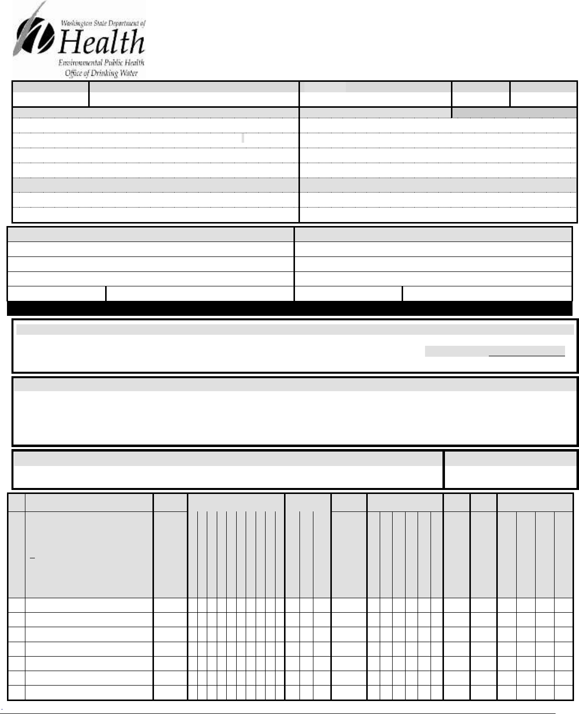
Group B Water System Design Guidelines (331-467) Page 85
September 2018
ONE FORM PER SYSTEM
1. SYSTEM ID NO.
2. SYSTEM NAME
3. COUNTY
4. GROUP
5. TYPE
6. PRIMARY CONTACT NAME & MAILING ADDRESS
7. OWNER NAME & MAILING ADDRESS
8. Owner Number:
ORGANIZATION NAME
ORGANIZATION NAME
PRIMARY CONTACT NAME TITLE:
NAME TITLE:
ADDRESS
ADDRESS
CITY STATE ZIP
CITY STATE ZIP
STREET ADDRESS IF DIFFERENT FROM ABOVE
STREET ADDRESS IF DIFFERENT FROM ABOVE
ADDRESS
ADDRESS
CITY STATE ZIP
CITY STATE ZIP
9. 24-HOUR PRIMARY CONTACT INFORMATION
10. OWNER CONTACT INFORMATION
Primary Contact Daytime Phone:
Owner Daytime Phone:
Primary Contact Evening Phone:
Owner Evening Phone:
Primary Contact Mobile/Cell Phone:
Owner Mobile/Cell Phone:
Fax:
Email:
Fax:
Email:
WAC 246-290-420()) requires water systems to provide 24-hour contact information for emergencies.
11. SATELLITE MANAGEMENT AGENCY – SMA (check only one)
Not applicable (Skip to #12)
Owned and Managed SMA NAME:__________________________________________ SMA Number: _______ ____
Managed Only
12. WATER SYSTEM CHARACTERISTICS (mark ALL that apply)
Agricultural
Hospital/Clinic
Residential
Commercial / Business
Industrial
School
Day Care
Licensed Residential Facility
Temporary Farm Worker
Food Service/Food Permit
Lodging
Other (church, fire station, etc.):
1,000 or more person event for 2 or more days per year
Recreational / RV Park
_________________________________
13. WATER SYSTEM OWNERSHIP (mark only one)
14. STORAGE CAPACITY (gallons)
Association
County
Investor
Special District
City / Town
Federal
Private
State
15.
16.
SOURCE NAME
17.
INTERTIE
18.
SOURCE CAPACITY
19.
USE
20.
21.
TREATMENT
22.
DEPTH
23.
24.
SOURCE LOCATION
LIST UTILITY’S NAME FOR SOURCE
AND WELL TAG ID NUMBER.
Example: WELL #1 XYZ456
IF SOURCE IS PURCHASED OR INTERTIED,
LIST SELLER’S NAME
Example: SEATTLE
INTERTIE
SYSTEM ID
NUMBER
WELL
WELL FIELD
WELL IN A WELLFIELD
SPRING
SPRING FIELD
SPRING IN A
SPRINGFIELD
SEAWATER
SURFACE WATER
RANNEY INF. GALLERY
OTHER
PERMANENT
SEASONAL
EMERGENCY
SOURCE METERED
NONE
CHLORINATION
FILTRATION
FLUORIDATION
IRRADIATION (UV)
OTHER
(DEPTH TO FIRST
OPEN INTERVAL)
CAPACITY
GALLONS PER MINUTE
¼, ¼ SECTION
SECTION NUMBER
TOWNSHIP
RANGE
S01
S02
S03
S04
S05
S06
S07
D
Group B Water Facilities Inventory (WFI) Form
For new or expanding Group B water systems only

Group B Water System Design Guidelines (331-467) Page 86
September 2018
Comments:
35. REASON FOR SUBMITTING WFI:
New System Other______________
ACTIVE
SERVICE
CONNECTIONS
DOH USE ONLY!
CALCULATED
ACTIVE
CONNECTIONS
DOH USE ONLY!
APPROVED
CONNECTIONS
25. SINGLE FAMILY RESIDENCES (How many of the following do you have?)
A. Full Time Single Family Residences (Occupied 180 days or more per year)
B. Part Time Single Family Residences (Occupied less than 180 days per year)
26. MULTIFAMILY RESIDENTIAL BUILDINGS (How many of the following do you have?)
A. Apartment Buildings, condos, duplexes, barracks, dorms
B. Full Time Residential Units in Apartments, Condos, Duplexes, Dorms that are occupied more than 180
days/year
C. Part Time Residential Units in the Apartments, Condos, Duplexes, Dorms, that are occupied less than 180
days/year
27. NONRESIDENTIAL CONNECTIONS (How many of the following do you have?)
A. Recreational Services (Campsites, RV Sites, Spigots, etc.)
B. Institutional, Commercial/Business or Industrial Services
28. TOTAL SERVICE CONNECTIONS
29. FULL-TIME RESIDENTIAL POPULATION
How many residents are served by this system 180 or more days per year? _______________________
30. PART-TIME RESIDENTIAL POPULATION
JAN
FEB
MAR
APR
MAY
JUN
JUL
AUG
SEP
OCT
NOV
DEC
A. How many part-time residents are present each
month?
B. How many days per month are they present?
31. TEMPORARY & TRANSIENT USERS
JAN
FEB
MAR
APR
MAY
JUN
JUL
AUG
SEP
OCT
NOV
DEC
A. How many total visitors, attendees, travelers, campers,
patients, or customers have access to the water system
each month?
B. How many days per month is water accessible to the
public?
32. REGULAR NONRESIDENTIAL USERS
JAN
FEB
MAR
APR
MAY
JUN
JUL
AUG
SEP
OCT
NOV
DEC
A. If you have schools, daycares, or businesses connected
to your water system, how many students, daycare
children, or employees are present each month?
B. How many days per month are they present?
33. ROUTINE COLIFORM SCHEDULE
JAN
N/A
FEB
N/A
MAR
N/A
APR
N/A
MAY
N/A
JUN
N/A
JUL
N/A
AUG
N/A
SEP
N/A
OCT
N/A
NOV
N/A
DEC
N/A
34. GROUP B NITRATE SCHEDULE
QUARTERLY
ANNUALLY
ONCE EVERY 3 YEARS
N/A
N/A
N/A
36. I CERTIFY THAT THE INFORMATION STATED ON THIS WFI FORM IS CORRECT TO THE BEST OF MY KNOWLEDGE.
SIGNATURE: DATE:
PRINT NAME: __________________ TITLE:

Group B Water System Design Guidelines (DOH 331-467) Page 87
September 2018
Appendix F
Group B Pump Test Guidance
Objective: To demonstrate that a proposed well (or wells) can provide sustainable and reliable
water production equal to or exceeding the minimum supply requirements needed to supply the
proposed number of water systems connections (WAC 246-291-125 (4)(d)). A pump test is the
best way to demonstrate this. A pump test is a well and localized aquifer stress test. It involves
recording and evaluating periodic measurement of pumping rate and water level changes during
a series of controlled pump and recovery (“rest”) test cycles. The results show how both the well
and the localized aquifer react to periods of intense pumping. Evaluating the degree of water
level drawdown and the rate of water level recovery helps to characterize the aquifer’s yield and
establish optimal well pump placement and operating conditions.
When executed correctly, a pump test provides sufficient information to demonstrate the
capacity of a well or collection of wells to produce enough water in a 24-hour period to service
the water system as designed.
• A successful pump test must show the proposed well (or combination of wells) can
provide a sustainable and reliable production of water (yield) equal to or exceeding the
minimum supply requirements in WAC 246-291-125 (4)(d) and recover to pre-pumping
level within a normal 24-hour operational period.
• A failed pump test is one that cannot demonstrate the required level of production and
recovery within a normal 24-hour operational period.
Part 1: Select and Run a Recommended Group B Pump Test
Pump Test
Procedure
Recommended Conditions for Use
Standard Step
Drawdown/Constant
Rate Test
See Appendix F-1
For sources located in:
• Fractured rock, shale, bedrock, or hard rock (consolidated) aquifers.
• Areas of known or suspected seawater intrusion.
• Aquifers with highly variable seasonal water tables.
• Aquifers with limited recharge.
• An area with nearby large capacity wells that could affect local water levels
and well yields.
Extended Step
Drawdown Test
See Appendix F-2
• Low projected water demand wells in a high-flow aquifer setting.
• Most common for small Group B systems with proposed wells in sand and
gravel aquifers.
Alternating Pump
and Recovery Test
See Appendix F-3
• Very small systems (2-6 connections), and
• Very low flow aquifer conditions, or
• Failure on other tests.
Part 2: Pump Test Report and Analysis:
The Pump Test Report (See Appendix F-4) documents the results of the pump tests, provides an
analysis of the well, and localized aquifer responses to the challenge of sustained pumping. The
designer can use that data to estimate aquifer characteristics, and determine pump and well
operational factors and well efficiency.

Group B Water System Design Guidelines (DOH 331-467) Page 88
September 2018
Elements of a complete report should discuss:
✓ Well yield.
✓ Expected operational drawdown.
✓ Pumping rates and recommended pump operational cycles.
✓ Recommended pump placement.
✓ Estimate of well efficiency.
✓ An estimate of the aquifer’s specific yield, hydraulic conductivity, or transmissivity (to
support evidence of sustainability and aquifer capacity consistent with proposed use of
the well).
If a pump test is unable to demonstrate a clear sustained yield as defined above, then the designer
should re-run the test with different operational assumptions and conditions (lower pumping rate,
add additional sources, or reduced total volume and associated connections). The designer might
need to consider using an alternative test.
Part 3: Additional considerations
• Low well yield contingency plan.
• Water quality test results.
• Risks of seawater intrusion (if appropriate).
• Reasons why stabilization was not achieved during testing.
• Well interference and well field considerations.
In challenging aquifer settings, a pump test can provide a starting point in the analysis and
potential mitigation of any localized aquifer conditions that could adversely affect long-term use
of the well (including concerns about saltwater intrusion, declining aquifer levels, consolidated
and fracture rock aquifers, aquifers with limited recharge, and high seasonal water level
variability). The pump test report is an appropriate place to highlight those issues and discuss
supply-related options.
Part 4: Recommended Pump Test Procedures:
The following sections lay out step-by-step procedures for the three recommended pump tests.
Site conditions and equipment must be factored into any pump test design and implementation.
While we recommend these procedures, they are still guidelines so the designer may modify
them based on professional expertise, experience, and on-site conditions. The result should be a
test, analysis and report that documents the sustainable use of the well as dictated by the water
system design criteria and the Group B rule.
In addition to the recommended pump test procedures, this Appendix includes data collection
templates for both the drawdown and recovery phases of a pump test. A successful test will
likely require multiple pages of each.
Examples of pump and recovery test data collected under the different test procedures are online
at
doh.wa.gov/CommunityandEnvironment/DrinkingWater/WaterSystemAssistance/GroupB/Group
BResources.aspx

Group B Water System Design Guidelines (DOH 331-467) Page 89
September 2018
Appendix F-1
Step Drawdown/Constant Rate Pump Test Procedure
Phase 1: Step Drawdown Pump Test
Objective: To evaluate well performance, and identify successful pumping conditions for
phase 2 of the pump test (constant rate). This information will allow a
determination of the optimal pump settings (depth and pumping rate) and well
efficiency for the well.
Elements:
1. We recommend that a qualified water professional (hydrogeologist or engineer) oversee
testing of the well and review data analysis and interpretations.
2. An access port to allow depth-to-water measurements must be installed, if not already
present, and maintained (WAC 173-160-355).
3. The step drawdown test should include at least four consecutive constant rate discharge
steps as described below, with a higher pumping rate used for each step. Each step should
be at least 60 minutes long.
4. The third step of the drawdown test should use a flow rate no less than the minimum
supply requirement in WAC 246-291-125 (4)(d). The remaining pumping rates should be
determined by multiplying this flow rate (in gallons per minute) by 0.50, 0.75, and 1.25.
5. Drawdown should be measured in the pumped well at least as frequently as the
following.
Time after pumping started
Time Intervals
0 to 10 minutes
1 minute
10 to 60 minutes
5 minutes
60 to 240 minutes
15 minutes
240 to 600 minutes
60 minutes
600 to 1,440 minutes
120 minutes
6. Recovery should be measured beginning at the end of the last step (immediately after the
pump is turned off) and ending when the water level returns to at least 95 percent of the
initial, pre-pumping static water level. Measurement frequency should follow the
specifications in the table above measured from the moment when pumping stopped.
Initial measurement intervals will be short and expand as recovery progresses. The pump
should not be removed until the water level returns to 95 percent of the pre-pumping
static water level.
7. Determine the maximum pumping rate and pumping depth as established from the step
drawdown test. Use these values for conducting the constant rate discharge test, if the test
is applicable.
Group B Water System Design Guidelines (DOH 331-467) Page 90
September 2018
Phase 2: Constant Rate Pump Test
Objective: To determine the capacity of the well and aquifer to provide a reliable yield of
water at the desired rate. The pumping and recovery data from the test can be used
to estimate aquifer transmissivity and a sustainable yield for the well. This test
procedure is recommended for sources in complex hydrologic settings where the
nature of the aquifer could adversely affect long-term continuous use of the
source. Sources with the potential for seawater intrusion should also conduct the
additional elements provided at the end of this document.
Elements:
1. We recommend that a qualified water professional (hydrogeologist or engineer) oversee
testing of the well.
2. An access port to allow depth to water measurements must be installed, if not already
present, and maintained (WAC 173-160-355).
3. The source should be pump tested at no less than the maximum rate determined from the
step drawdown test. The constant rate discharge test should not be conducted until after
the water levels in the aquifer have achieved at least 95 percent recovery from the step
drawdown test pre-pumping static water level conditions.
4. The constant rate discharge test should be at least 24 hours long. If, at 24 hours, four
hours of stabilized drawdown have been observed, the pump may be shut off and
measurements of recovery begun. If stabilized drawdown has not been observed within a
total of 36 hours, the pump may be shut off and recovery measurements begun.
Stabilization is defined as a drop in water level of less than or equal to 0.1 feet per hour.
5. Drawdown should be measured in the pumped well at least as frequently as:
Time after pumping started
Time intervals
0 to 10 minutes
1 minute
10 to 60 minutes
5 minutes
60 to 240 minutes
30 minutes
240 to 600 minutes
60 minutes
600 to 1440 minutes
120 minutes
6. Proper sampling procedures must be used to collect water samples from the source and a
DOH-certified lab must analyze them. Water samples must be taken within the last 15
minutes of pumping and analyzed for the following water quality parameters:
• Coliform (bacteria): Two coliform samples required (WAC 246-291-170(2)(a)).
• Inorganic Chemicals (IOCs).
• Additional Volatile and/or Synthetic Organic Chemicals (VOCs /SOCs).*
*If required by DOH because the well is in areas of known or expected contamination
7. After pumping, you should collect recovery data until 95 percent recovery of the pre-
pumping static water level is achieved. You should measure recovery in the same manner
and at the same frequency as the table above. To facilitate accurate recovery data
collection, the pump test piping should incorporate backflow check-valve(s) that prevent
water within the riser pipe from flowing back into the well when the pump is shut off.

Group B Water System Design Guidelines (DOH 331-467) Page 91
September 2018
8. When the pumping test is completed, you should compile the data into a report and
submit it to DOH. The report should include the following.
a. All data on pumping rates and water levels (including static water levels) from the
pumping test and recovery period, and appropriate graphical presentations of the data.
b. An estimate of the aquifer’s specific yield, hydraulic conductivity, and transmissivity
(to support evidence of sustainability and aquifer capacity consistent with proposed
use of the well).
c. A map and description (¼, ¼, Section Township Range) accurately indicating the
well location, and the land surface elevation to the nearest foot above sea level.
Address and parcel number should be provided.
d. Summary, conclusions, and recommendations on pump settings, operational regimes,
and source reliability.
e. A well construction report (well log) for the pumping well and all observation wells
(if any).
f. Distance, to the nearest foot, from pumping well to all observation wells and a map
indicating all well locations.
g. A copy of all laboratory test results.
Additional Steps for Potential Seawater Intrusion Areas
▪ For the source well (the well pumped during the aquifer test), chloride and conductivity
samples should be collected at the following intervals:
o One sample during the initial 30 to 60 minutes.
o One sample during the 6
th
hour (360 to 420 minutes).
o One sample during the 12
th
hour (720 to 780 minutes).
o One sample within the last 15 minutes of the aquifer test pumping phase.
▪ An observation well, if one is available, should be pumped by an amount equal to three times
the volume of water inside its well casing before collecting chloride and conductivity
samples. Following collection of these samples, an observation well should be given
adequate time to recover to static water level before initiating the production well aquifer test
(pump test). At the completion of the production well aquifer test (including complete
recovery), another set of chloride and conductivity samples should be collected from the
observation well. Note: We recommend that a field test kit be used to monitor chloride levels
within the pumping well during the pumping phase.
The report should include the following.
1. Tidal influence on the pumping well. Data on pumping water levels, chlorides,
and tidal fluctuations (corrected to point) should be plotted on a single graph with
respect to time.
2. Potential for seawater intrusion into this or other seaward wells.

Group B Water System Design Guidelines (DOH 331-467) Page 92
September 2018
Appendix F-2
Extended Step Drawdown Pump Test Procedure
Objective: To evaluate well performance and determine whether a source over an aquifer
with an expected high yield can produce a sustainable yield. The test results can
be used to determine optimal pump settings and well efficiency. The extended
pumping and recovery data is used to estimate aquifer transmissivity and confirm
that there are no underlying aquifer conditions likely to adversely affect long
term use of the source. This test is most appropriate for sources with a small
demand within a high yield aquifer.
Elements:
1. We recommend that a qualified water professional (hydrogeologist or engineer) oversee
testing of the well and review data analysis and interpretations.
2. An access port to allow depth to water measurements must be installed, if not already
present, and maintained (WAC 173-160-355).
3. The step drawdown test should include at least four consecutive constant rate discharge
steps, with a higher pumping rate used at each step. The first three steps should be at least
60 minutes long. The fourth step is extended until 4 hours of stabilization occurs or until
12 hours total pumping time has elapsed. Stabilization means less than 0.1 foot of
drawdown fluctuation per hour in 4 hours of drawdown measurement.
4. The third step of the drawdown test should use a flow rate no less than the
minimum supply requirement in WAC 246-291-125 (4)(d). The remaining
pumping rates should be determined by multiplying this flow rate (in gallons per
minute) by 0.50, 0.75, and 1.25.
5. Drawdown should be measured in the pumped well at least as frequently as the
following.
Time After Pumping
Started
Time Intervals
0 to 10 minutes
1 minute
10 to 60 minutes
5 minutes
60 to 240 minutes
15 minutes
240 to 600 minutes
60 minutes
600 to 1440 minutes
120 minutes
6. You must use proper sampling procedures to collect water samples from the source and a
DOH-certified lab must analyze them. Water samples should be taken within the last 15
minutes of pumping and must be analyzed for the following water quality parameters:
• Coliform (bacteria): Two coliform samples required (WAC 246-291-170(2)(a)).
• Inorganic Chemicals (IOCs).
• Additional Volatile and/or Synthetic Organic Chemicals (VOCs /SOCs).*
*If required by DOH because the well is in an area of known or expected contamination.

Group B Water System Design Guidelines (DOH 331-467) Page 93
September 2018
7. Measure recovery beginning at the end of the last step (immediately after the pump is
turned off) and ending when the water level returns to within 95 percent of the initial,
pre-pumping static water level. Measurement frequency should follow the specifications
in the table above measured from the moment pumping stopped. Initial measurement
intervals will be short and expand as recovery progresses. The pump should not be
removed until the water level returns to 95 percent of the pre-pumping static water level.
8. Determine the maximum pumping rate and pumping depth as established from the step
drawdown test. Use the data from this final step to plot the time (drawdown graph) and
determine transmissivity, storage coefficient, and hydraulic conductivity.
9. When the pump test is complete, compile the data into a report and submitted to DOH. It
should include the following.
a. All data on pumping rates and water levels (including static water levels) from the
pumping test and recovery period, and appropriate graphical presentations of the data.
b. An estimate of the aquifer’s specific yield, hydraulic conductivity, and transmissivity
(to support evidence of sustainability and aquifer capacity consistent with proposed
use of the well).
c. A map and description (¼, ¼, Section Township Range) accurately indicating the
well location and the land surface elevation to the nearest foot above sea level.
Address and parcel number should be provided.
d. Summary, conclusions, and recommendations on pump settings, operational regimes,
and source reliability.
e. A well construction report (well log) for the pumping well and all observation wells
(if any).
f. Distance, to the nearest foot, from pumping well to all observation wells and a map
indicating all well locations.
g. A copy of all laboratory test results.

Group B Water System Design Guidelines (DOH 331-467) Page 94
September 2018
Appendix F-3
Alternating Pump and Recovery Test
Objective: To evaluate whether a proposed source in a low-flow environment can produce the
estimated daily demand and recover within a 24-hour operational period. You should
use this test only when aquifer yield is low and cannot maintain the sustained periods
of pumping needed for either a step-drawdown or a constant-rate test. The pumping
and recovery data obtained during the test will help identify a sustainable operating
regime that supports approval of a water source for a Group B water system.
Elements:
1. Because of the complex and nonstandard nature of this test, we recommend that a
licensed water resource professional direct the work needed to complete it.
2. An access port to allow depth-to-water measurements must be installed, if
not already present, and maintained (WAC 173-160-355).
3. The test consists of a series of alternating pump and recovery cycles.
▪ Each pumping cycle should last for a standard period of time at an intermediate flow
rate (usually two to six hours). At the end of that time, the pump is turned off and
water levels are allowed to recover to pre-pumping or near normal condition. During
both pumping and recovery parts of the cycle, water levels are recorded at the time
intervals described below.
▪ The pump and recovery cycle is continued for at least 24 hours or until the combined
pumped volume equals or exceeds the maximum daily demand. Pumping rate and
periods can be changed between cycles, but pumping rate must be constant within
each cycle. Pumping time, volume pumped and water level changes must be recorded
for each cycle. Pumping periods should be no shorter than two hours.
▪ Because of the iterative nature of the test, it may be necessary to run the test longer
than 24 hours to identify the appropriate combination of operational conditions that
will produce maximum daily demand and still allow for recovery within a 24-hour
operational regime.
▪ The pump test cycle must be repeated until a combined pumping volume from
all pump cycles has produced a total volume in excess of the minimum
maximum daily demand for the proposed system. The test is not complete
until recovery occurs after the last pump cycle is completed.
4. Drawdown and recovery should be measured in the pumped well for each pump and
recovery cycle at least as frequently as the following.
Time after pumping started
Time intervals
0 to 10 minutes
1 minute
10 to 60 minutes
5 minutes
60 to 240 minutes
15 minutes
240 to 600 minutes
60 minutes
600 to 1440 minutes
120 minutes

Group B Water System Design Guidelines (DOH 331-467) Page 95
September 2018
5. Water samples must be collected from the source using proper sampling
procedures and analyzed by a DOH-certified laboratory. Water samples should be
taken within the last 15 minutes of pumping and must be analyzed for the
following water quality parameters:
• Coliform (bacteria): Two coliform samples required (WAC 246-291-170(2)(a)).
• Inorganic Chemicals (IOCs)
• Additional Volatile and/or Synthetic Organic Chemicals (VOCs /SOCs)*
*If required by DOH because the well is in an area of known or expected contamination.
6. Recovery should be measured beginning at the end of each pump cycle (immediately
after the pump is turned off) and ending when the water level returns to within 95 percent
of the initial, pre-pumping static water level. Measurement frequency should follow the
specifications in the table above.
7. Determine the maximum pumping rate and pumping depth and plot the time (drawdown
graph) and recovery data to determine transmissivity, storage coefficient, and hydraulic
conductivity.
8. When the pump test is complete, the data should be compiled into a report and submitted
to DOH. The report should include:
a. All data on pumping rates and water levels (including static water levels) from the
pumping and recovery periods, and appropriate graphical presentations of the data.
b. An estimate of the aquifer’s specific yield, hydraulic conductivity, and transmissivity
(to support evidence of sustainability and aquifer capacity consistent with proposed
use of the well).
c. A map and description (¼, ¼, Section Township Range) accurately indicating the
well location and the land surface elevation to the nearest foot above sea level.
Address and parcel number should be provided.
d. Summary, conclusions, and recommendations on pump settings, operational regimes,
and source reliability.
e. A well construction report (well log) for the pumping well and all observation wells
(if any).
f. Distance, to the nearest foot, from pumping well to all observation wells and a map
indicating all well locations.
g. A copy of all laboratory test results.

Group B Water System Design Guidelines (DOH 331-467) Page 96
September 2018
Appendix F-4
Pump Test Data Collection Form
System ID:
Owner:
Well Tag No.:
DOH Source ID:
System Name:
Well Name:
Type of Test:
Conducted By:
Date:
Static Water Level (as measured from reference point):
County:
Observation Wells?
Well Elevation (MSL):
Distance of observation well (r) from pumped well (ft):
Time
Time (t) since
pumping
began
(min)
Depth to
Water
Level (ft)
Drawdown
(ft)
t/r
2
Pumping
Rate (Q)
[gpm]
Comments

Group B Water System Design Guidelines (DOH 331-467) Page 97
September 2018
Recovery Data Collection Form
System ID:
Owner:
Well Tag No.:
DOH Source ID:
System Name:
Well Name:
Type of Test:
Conducted By:
Date:
Static Water Level (as measured from reference point):
County:
Observation Wells?
Well Elevation (MSL):
Distance of observation well (r) from pumped well (ft):
Time
Time (t)
since
pumping
began
(min)
Time (t’)
since
pumping
stopped
(min))
t/t’
Depth
to
Water
Level
(ft)
Residual
Drawdown
(ft)
Comments

Group B Water System Design Guidelines (DOH 331-467) Page 98
September 2018
Appendix G
Pump Cycle Control Valves
A pump cycle control valve (CCV) may be used to control the pressure in a distribution system.
The CCV is intended to extend run time with minimal pressurized storage. It will maintain
constant downstream pressure (i.e., the valve’s set point) until demand downstream of the valve
falls below the valve’s prescribed low flow level, at which point the pressure will rise to the
pressure switch pump-off set point. The valve is mechanically prevented from restricting flow
past its preset minimum.
Pressurized storage is needed with the CCV to supply the distribution system when demand falls
below the valve’s minimum flow setting and pump operation gets shut down. The size of the
pressure tank(s) will depend on several factors as described below, but the size and number
always will be less than that required if a cycle control valve had not been installed. Designers
should review manufacturer’s recommendations to ensure all valve application requirements are
met.
Advantages of using a CCV include:
1. Limiting well pump on-off cycling and the associated wear on water system components.
2. Reducing the size or number of pressure tanks required for any given installation.
3. Reducing the potential for damaging transient pressure waves (“water hammer”) resulting
from hard pump-start and pump-stop conditions.
Design considerations and challenges of using a CCV include:
• The valve must be listed under NSF standard 61 for potable water supply use (see WAC
246-291-205)
• The control valve itself can impose significant energy loss (“head loss”) at the high end
of its flow range when fully open (a 1¼-inch control valve causes the loss of about 10 psi
at 50 gpm). The well pump design must account for the head loss imposed by the control
valve.
• It is difficult to predict whether the savings through limiting the number of “pump-start”
events and reduced initial capital cost associated with fewer bladder tanks will offset the
cost of the additional energy used in prolonging the pump-on portion of the cycle.
• Water quality may affect control valve performance. Particulate matter (sand) may
adversely affect the performance of the control valve.
• At low flow conditions, the pressure on the upstream side of the control valve will be
near the pump’s shut-off head. You should pay attention to the design, material
specifications, and construction of the pump to ensure it can operate near its shut-off head
for extended periods, and to the pressure rating of the piping and valves on the upstream
side of the control valve.
• CCV consumes greater amounts of energy per gallon pumped due to prolonged operation
at low pump efficiency.

Group B Water System Design Guidelines (DOH 331-467) Page 99
September 2018
The CCV is usually installed between the pump(s) and the pressure tank(s). The valve’s
downstream pressure setting should fall between the pressure switch on and off pressure settings.
As the demand in the water system varies, the cycle control valve adjusts the pressure generated
by the pump by modulating the size of the valve opening. The pump-on phase of the pump cycle
will continue until the water system demand drops below the valve’s minimum flow setting. At
this point, pump supply in excess of system demand goes into pressurized storage until the
pressure tank reaches the pressure switch “pump-off” setting. If demand (including leaks) never
drops below the valve’s minimum flow setting, the pump will never shut off.
While the pump is off, all water demand is satisfied by water released from the pressure tank(s).
The length of the “pump-off” period depends on water system demand and the available
withdrawal volume of the pressure tank(s).
The number of pump starts per hour is important since pump motors may be damaged by
excessive heat build-up from too-frequent starts. In the absence of the pump motor
manufacturer’s specification, pump starts should be limited to no more than six (6) per hour.
In order to design the pressure tank system so pump starts are limited to no more than six starts
per hour (or per the manufacturer’s specification), designers should consider:
• The valve’s minimum flow setting and pre-set downstream pressure setting;
• Pump-on and pump-off pressure setting; and
• Where the valve pressure set-point falls within the pump-on-off pressure range.
Example
Given:
• Bladder tank system
• Pump on pressure = 40 psi
• Pump off pressure = 60 psi
• Cycling control valve pressure setting = 50 psi
• Pump control valve low-flow setting = 5 gpm
Find:
• Volume (“V”) of pressurized storage between 60 and 40 psi available to the distribution
system while the pump is off to provide for a minimum pump cycle time of 10 minutes
(equal to 6 cycles per hour)
Solution:
• The shortest pressure tank fill time + tank draw time occurs when distribution system
demand is approximately equal to one-half the low-flow valve setting (2.5 gpm in this
example). System demand is “Y” and valve flow setting is “X”.
• To simplify and remain conservative, assume the time to fill the pressure tank from the
low-pressure pump-on setting (i.e., 40 psi in this example) to valve pre-set pressure
setting (i.e., 50 psi) is instantaneous. Also, assume pressurized volume from 40 psi to 50
psi is equal to the pressurized volume from 50 psi to 60 psi.
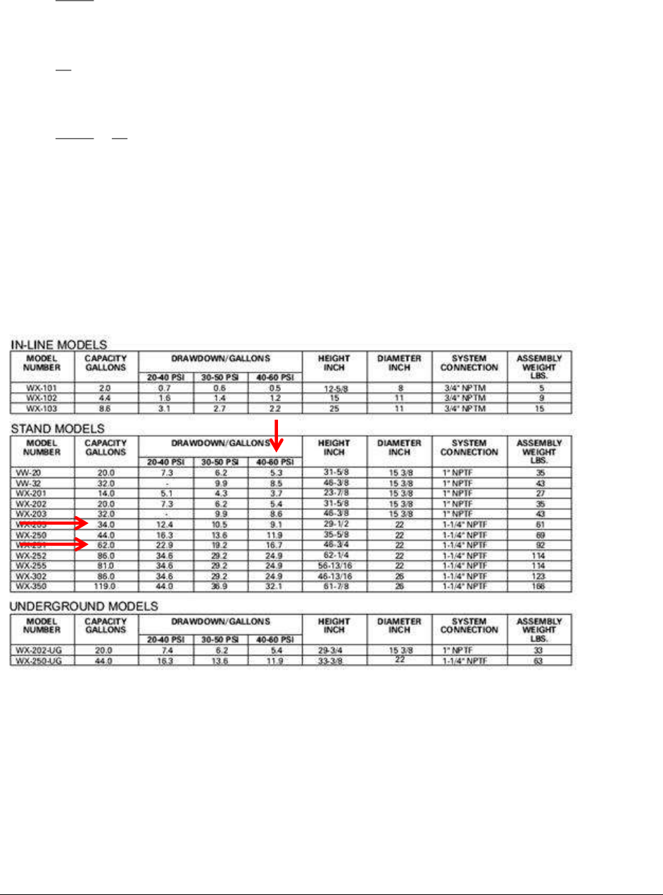
Group B Water System Design Guidelines (DOH 331-467) Page 100
September 2018
• Time to fill pressure tank from 50 psi to 60 psi:
Y-X
5.0 V
• Time to draw down pressure tank from 60 psi to 40 psi while pump is off:
Y
V
• Solve this equation:
Y-X
5.0 V
+
Y
V
= 10 minutes = 6 cycles per hour
If X = 5 gpm and Y = 2.5 gpm, then V = 16.7 gallons
In the above example, the bladder tank system must provide at least 16.7 gallons of storage
between 40 psi and 60 psi. Based on the following pressure tank manufacturer’s information, the
drawdown for a nominal 34-gallon pressure tank is 9.1 gallons from 40-60 psi. In order to
provide 16.7 gallons, two 34-gallon pressure tanks are needed. Alternately, one 62-gallon
pressure tank will satisfy the pressurized storage requirement.

Group B Water System Design Guidelines (DOH 331-467) Page 101
September 2018
Appendix H
Variable Frequency Drive Pumps and Motors
A variable-frequency drive (VDF) is an electronic controller that adjusts the speed of an electric
motor by modulating frequency and voltage. VFDs provide continuous control by matching
motor speed to the specific demands of the work being performed. VFDs allow operators to fine-
tune pumping systems while reducing costs for energy and equipment maintenance.
Use in potable water systems
VFDs are becoming more popular at water facilities, where the greatest energy demand most
often comes from pump motors – an application particularly suited to variable-frequency drives.
VFDs enable pumps to accommodate fluctuating demand, running pumps at lower speeds and
drawing less energy while still meeting water system needs.
Benefits
Single-speed drives start motors abruptly, subjecting the motor to high torque and current surges
up to 10 times the full-load current. In contrast, variable-frequency drives offer a “soft start”
capability, gradually ramping up a motor to operating speed. This lessens mechanical and
electrical stress on the motor system, can reduce maintenance and repair costs, and extend motor
life.
VFDs allow more precise control of processes, such as water production and distribution. They
can also maintain pressure in water distribution systems to closer tolerances. Energy savings
from VFDs can be significant. Affinity laws for centrifugal pumps suggest that a reduction in
motor speed will generate energy savings. While motor speed and flow are proportional (e.g.,
75% speed = 75% flow), motor speed and horsepower have a cubed relationship (e.g., 75%
speed = 40% power consumption). Despite some of the VFD controller’s additional energy
requirements, VFDs can reduce a pump’s energy use over many single-speed pumping
applications.
Pumps may be designed and installed for the built-out condition, and operate economically and
efficiently for the many years it will take to reach the full demand design condition.
Disadvantages and Design Challenges
• Outdoor installations can be a problem, since VFDs can’t tolerate extremely cold
weather. Check the manufacturer’s specifications for ambient air temperature limitations.
• VFD controllers are sensitive to high temperature and particulates. The manufacturer
should be consulted on the need for air conditioning and air filtering.
• Placing the controller more than 100 feet from the motor can be a problem without taking
special provisions. Check with the VFD manufacturer for specific requirements.
• Power and control wires must be in separate conduits.
• VFDs only work on three-phase motors, except in very small pump applications.
• Pumps controlled by a VFD may not meet the minimum water flow required to keep the
motor winding cool. Care should be taken to ensure that the pump is not operating below

Group B Water System Design Guidelines (DOH 331-467) Page 102
September 2018
this speed. Sleeving may also be an option to protect the pump motor. Confirm with the
submersible pump manufacturer the minimum flow rate across the motor needed for
motor cooling.
• The quality of the power coming into the VFD controller can have a significant impact on
controller performance. Voltage fluctuations should be monitored prior to installing a
VFD controller.
• Experienced electronics personnel will be required for maintenance and repair.
When designing a VFD pumping system
Certain rotational speeds may induce resonance and excessive vibration. Designers should check
with the manufacturer the resonant frequency of the pump/motor, and whether that frequency
could be induced by a speed within the predicted operating range of the pump.
The designer should reference the minimum flow requirements of the pump when establishing
the operating range of the pumping system. Each manufacturer will have its own specific
requirements for pressurized storage volume to ensure compatibility with the specific low-flow
pump off discharge rate, ramping speed, and the system control pressure range.

Group B Water System Design Guidelines (DOH 331-467) Page 103
September 2018
Appendix I
Water Treatment Plant Wastewater Disposal
Water treatment plants (WTP) that discharge wastewater are considered industrial dischargers,
no matter where they discharge their wastewater (land or surface water). The Department of
Ecology is the lead agency in permitting all water treatment plant wastewater discharges. Most
discharges must be covered under either a National Pollutant Discharge Elimination System
(NPDES) permit (general or individual), or a state waste discharge permit.
Conditionally Exempt WTP Wastewater Discharges
WTPs are considered “conditionally exempt” from state-based permit requirements for waste
discharge to ground if they meet all of the following conditions. This exemption is subject to
periodic review of WTP processes and discharge characteristics by Ecology. Part of Ecology’s
review includes a determination of whether a “reasonable potential to pollute” exists, based on
the methods in the U.S. EPA “Technical Support Document for Water Quality-Based Toxics
Control,” March 1991, EPA/505/2-90-001.
1. Discharge must be free of additives that have the potential to reach waters of the state,
with the exception of up to 20 lbs. of salt per day used in ion exchange, provided the
brine discharge is not to a shallow aquifer, highly permeable soils, an aquifer with limited
recharge, or in a location where ground-water quality is threatened.
2. Infiltration ponds/trenches must have sufficient free board to prevent over-topping and be
managed so that there is no reasonable potential to discharge to surface water.
3. Discharge must not result in unmanaged soil erosion or deterioration of land features.
4. Residual solids that accumulate in infiltration ponds/trenches must be disposed of as
necessary to avoid a build-up and concentration of these materials.
5. Disposal of solids must be consistent with requirements of the local health jurisdiction.
Discharge to a “dry well” is technically underground injection and is prohibited under the State’s
Underground Injection Control Act, Chapter 173-218 WAC. Discharge to a drain field,
infiltration pond, or trench, although not prohibited, should be used only when discharge via land
application (irrigation) or into a grass-lined swale is not possible. Wastewater discharges must be
properly managed so that there is no reasonable potential to discharge to surface water, cause soil
erosion, or deteriorate land features.
The following tables provide a general summary of agency oversight and applicable permitting
requirements for various WTP waste discharge scenarios. Table 3 contains information most
likely applicable to nitrate treatment plant wastewater discharges.

Group B Water System Design Guidelines (DOH 331-467) Page 104
September 2018
Table 1
Less than 50,000 gpd finished water production
Treatment is not IX, RO, or Slow Sand Filtration
Waste Stream Characteristics
(daily volume, content, etc.)
Disposal
Method
Agency with
Regulatory Oversight
Authority
Wastewater (not the settled sludge)
generated by filter backwash (including from microfiltration and
ultrafiltration), sedimentation/presedimentation basin
washdown, sedimentation/clarification, and filter-to-waste
processes
Discharge to
surface water
Department of Ecology
No NPDES or state waste
discharge permit required –
considered to have no
reasonable potential to pollute.
Wastewater (not the settled sludge)
generated by filter backwash (including from microfiltration and
ultrafiltration), sedimentation/presedimentation basin
washdown, sedimentation/clarification, and filter-to-waste
processes
Discharge to
ground
Department of Ecology
Site-specific: May need a state
waste discharge permit. See
conditionally exempt narrative
above.
Wastewater (not the settled sludge)
generated by filter backwash (including from microfiltration and
ultrafiltration), sedimentation/presedimentation basin
washdown, sedimentation/clarification, and filter-to-waste
processes
Discharge to
POTW
Local municipality
Settled sludge (from wastewater)
generated by filter backwash (including from microfiltration and
ultrafiltration), sedimentation/presedimentation basin
washdown, sedimentation/clarification, and filter-to-waste
processes
Agronomic or
silvicultural
use
Land application:
Local health jurisdiction
Statewide Beneficial Use
Determination:
Department of Ecology
Settled sludge (from wastewater)
generated by filter backwash (including from microfiltration and
ultrafiltration), sedimentation/presedimentation basin
washdown, sedimentation/clarification, and filter-to-waste
processes
Landfill
Local health jurisdiction

Group B Water System Design Guidelines (DOH 331-467) Page 105
September 2018
Table 2
Any treatment plant finished water production capacity
IX, RO, EER, Microfiltration, Ultrafiltration, or Nanofiltration
Waste Stream Characteristics
(daily volume, content, etc.)
Disposal
Method
Agency with
Regulatory Oversight
Authority
IX or RO brine, or filter backwash that contains dissolved
solids removed from the source water (consisting of
regeneration liquid, ionic pollutants, and rinse water)
Discharge to
surface water
Department of Ecology
Individual NPDES permit,
except for discharges from
desalinization processes of up
to 5,000 gpd to salt waters.
IX or RO brine, or filter backwash that contains dissolved
solids removed from the source water (consisting of
regeneration liquid, ionic pollutants, and rinse water)
Discharge to
ground
Department of Ecology
Site-specific: May need a state
waste discharge permit. See
conditionally exempt narrative
above.
IX or RO brine, or filter backwash that contains dissolved
solids removed from the source water (consisting of
regeneration liquid, ionic pollutants, and rinse water)
Discharge to
POTW
Local municipality and
Department of Ecology
Site-specific: May need a state
waste discharge permit.
IX or RO brine, or filter backwash that contains dissolved
solids removed from the source water (consisting of
regeneration liquid, ionic pollutants, and rinse water)
Agronomic or
silvicultural
use
Department of Ecology
Site-specific: May need a state
waste discharge permit. See
conditionally exempt narrative
above.
Settled sludge (from wastewater)
generated by filter backwash, sedimentation/presedimentation
basin washdown, sedimentation/clarification, and filter-to-waste
processes
Landfill or
recycling
Local health jurisdiction
EER = Electrodialysis/electrodialysis reversal
IX = Ion exchange
RO = Reverse osmosis
The main assumption for this table is that wastes and discharges are "typical," i.e., they do not contain unusually
large amounts of pollutants.
Single domestic or point-of-use IE or RO systems do not require a state waste discharge permit because they are
considered to have no reasonable potential to pollute.
