
www.mottcorp.com
1
Mott Corporation
SINTERED POROUS METAL FILTRATION SYSTEMS FOR
PETROLEUM REFINING APPLICATIONS
Dr. Kenn
eth L. Rubow
Louise L. Stange
Mott Corporation
Presented at the
A
merican
F
iltration and Separation Society Conference
Galveston, TX
April 9
-
12, 2002

www.mottcorp.com
2
Mott Corporation
S
INTERED POROUS METAL
FILTRATION SYSTEMS
FOR
PETROLEUM REFINING A
PPLICATIONS
Abstract:
Currently, petroleum products are the largest source of energy used in United
States, with 90 percent of these products being fuels such as gasoline, coke, kerosene
,
aviation fuels, distillate, residual oil and liquefied petroleum gas. Refineries convert
petroleum oil into finished products through physical, thermal and chemical separation
processes. Other materials produced by refineries include non
-
fuel petrochemi
cal
products such as ethylene, propylene and benzene used to manufacture chemicals and
plastics.
Stringent environmental regulations, safety concerns and productivity improvements
often necessitate modifying existing refinery and petrochemical processing
technology.
Reformulation of gasoline to reduce auto emissions and EPA regulations concerning the
handling of spent FCC catalyst have encouraged refineries to evaluate their catalyst
management strategy. Advances in filtration technology and filter media s
upport
improvements in catalyst recovery applications which improve overall product yield,
increase the market value of the filtered product, reduce wear and tear of downstream
equipment and minimize operator exposure to hazardous materials. This paper wil
l
discuss filter
-
operating parameters of sintered porous metal media and filtration system
design criteria for optimizing performance in the removal of catalyst fines from slurry oil.
INTRODUCTION
Petroleum refiners use a process called Fluid Catalytic
Cracking (FCC) to convert heavy
petroleum fractions into products such as gasoline, kerosene and feedstock for
petrochemical processes. The conversion of crude oil fractions into higher value
products requires the use of catalysts. The product stream from
the FCC unit contains
silica and alumina fines generated from catalysts used in the process. After distillation,
these fines are concentrated in the heaviest fraction or slurry oil.
Filtration systems designed for the removal of catalyst fines from slur
ry oil utilizing
sintered porous metal media were introduced in the mid 1980’s. Filtration of slurry oil
using an advanced filtration system design and sintered metal media continue to
demonstrate long term filter operating performance in the separation of
FCC catalyst
fines from slurry oil to reduce the ash content. Unlike centrifuges or electrostatic
techniques, the filtration media acts as a positive barrier to remove downstream catalyst
contamination
.
Sintered metal filtration technology using inside
-
ou
t filtration
configuration provides a reliable method of achieving high quality slurry oil product by
reducing catalyst content
.
1
The
backwash capability of the media provides an economic
alternative to the use of settling tanks. Removal of the fines incre
ases FCC product
yield, improves the market value of the filtered product and reduces wear and tear of
downstream equipment in addition to improving the catalyst recover and handling
process.

www.mottcorp.com
3
Mott Corporation
There are numerous grades and manufacturers of catalyst since
FCC was introduced in
the early 1940’s. Filtration feasibility testing continues to be an effective means in media
selection and verification of filter operating parameters to confirm process scale
-
up
design for commercial installations. Feasibility testin
g is recommended as catalyst fines
vary in size, with a range from submicron to 30
-
40 microns, and occasionally larger.
PRINCIPLE FEATURES A
ND PROPERTIES OF SIN
TERED METAL MEDIA
The primary characteristics of sintered metal media that make it well sui
ted for refinery
applications are strength, durability and pressure capacity. The inherent durability of
metal filters allows for continuous, backwash operation for extended periods. Sintered
metal media are manufactured by pressing pre
-
alloyed powders eit
her as tubes or as
porous sheet, followed by high temperature sintering. The combination of powder size,
pressing and sintering conditions defines the pore size and distribution, strength and
permeability of the porous element. The filter media is designed
and engineered with a
stable porous matrix, precise bubble point specification, close thickness tolerance and
uniformity of permeability, which assure reliable filtration performance, effective
backwash cleaning and long on
-
stream service life.
Pore size
of sintered metal media is determined using ASTM E
-
128 standard procedure
that relates pore size to the pressure required to expel a liquid from a capillary of a
certain diameter by gas. The media grade designation is equivalent to the mean flow
pore, or
average pore size of the filter. Sintered metal media are offered in grades 0.1,
0.2, 0.5, 1, 2, 5, 10, 20, 40 and 100.
Typically, 316L stainless steel grades 0.5 and 2 media are recommended for refinery
applications. The all
-
welded construction of porou
s media to hardware is an additional
advantage for high temperature and the abrasive nature of the slurry oil. Other corrosion
resistant alloys include: Stainless Steel 304 L, 310, 347, and 430; Hastelloy
®
2
B, B
-
2, C
-
22, C276, N and X; Inconel
®
600, 625, a
nd 690; Monel
®
400
3
; Nickel 200; Alloy 20;
Titanium.

www.mottcorp.com
4
Mott Corporation
Filter Media Selection for Removal of FCC Catalyst Fines
Due to variations in slurry oil viscosity, catalyst particle size and slurry concentration of
each refinery process the preferred method of se
lecting filter media is via laboratory or
pilot trials. Feasibility tests verify filter
-
operating parameters such as particle removal
efficiency, pressure drop vs. solids loading, recovery pressure after backwash and cycle
length. Experience in similar ser
vice may be the basis for filter selection, taking into
account the specific solids and liquid of the process and if actual test data cannot be
obtained.
The particle size range of catalyst material varies with the operating performance of the
FCC unit.
FCC catalysts are broadly classified on the basis of the method of
manufacture: silica or clay based and active alumina. The mechanical integrity of the
catalyst combined with cyclone efficiency influence solids concentration and catalyst
particle size dis
tribution of the slurry oil. Optimum filtration results are obtained with a
broad particle size distribution.
Cyclones are the first stage of catalyst fines removal in the FCC unit. Efficiently
operating cyclones can remove sufficient fines from the react
ion product to produce
slurry oil with solids content of about 0.2% by weight (2000 ppm) or lower.
4
Slurry oil
concentration evaluated in laboratory and pilot tests is typically between 500
-
1500 parts
per million (ppm) total suspended solids (TSS).
The
variations of the FCC catalyst
fines distribution are shown in
Figure 1. Normal catalyst fines
particle size distribution observed in
FCC cyclones is typically a normal
bell curve ranging from < 5 to 80
µm, with a peak in the 30
–
40 µm
range. Bimodal dis
tributions are the
result of either attrition of the
catalyst or damage to the cyclone or
plenum.
Attrition of the catalyst causes the
curve to shift to the left, with a peak
in the 2
–
3 µm range. Fracturing
catalyst at a high velocity stream
generates
submicron particles. A
shift to the right of the normal bell
shaped curve with a peak in the range
of 40 µm or greater is the result of full
-
range catalyst being drawn into the cyclone or plenum.
5
0
20
40
60
80
100
0
5
10
15
20
25
FCC Catalyst Fines Distribution
Wt. %
Particle Size, µm
Normal Distribution
Attrition
Damaged Cyclone
Figure 1. FCC catalyst fines distribution

www.mottcorp.com
5
Mott Corporation
Catalyst with a small mean particle size and narrow distr
ibution will usually require a
finer media grade and will filter more slowly. A larger mean particle size and broader
distribution will work with a coarser media grade at a slightly higher operating flux.
Sintered metal
media grades 0.5 and 2 are typica
lly recommended for refinery
applications. For applications with a catalyst particle size distribution that tends to shift
to the left of the normal distribution, grade 0.5 media ensures that the catalyst particles
are removed on the media surface preventi
ng media plugging and ensuring removal
efficiency.
Refineries have recognized improvements in filtration technology using sintered metal
cartridge filters for catalyst removal. Filtration evaluation of slurry oil streams from more
than 50 refinery locat
ions continue to show significant variation in catalyst particle and
distribution range. Samples evaluated to date have an average particle size range of
1
-
40 µm, with a mean size (based on volume %) of 15 µm. Laboratory and pilot testing
continues to b
e a reliable means to validate filter operating performance.
Table 1 summarizes several pilot studies conducted to evaluate filtrate quality using
grades 0.5, 2 and 5 media. Testing with grade 0.5 media and fine catalyst of less than
10 µm in size resul
ted in filtrate quality (based on ash analysis) of less than 20 ppm
TSS. Other refineries with larger catalyst fines have achieved similar filtrate quality with
grade 2 media. Tests using grade 5 media had the highest ash content measuring 91
ppm TSS.
F
iltration Principle
Sintered metal filters are high efficiency, two
-
dimensional, straining type with particulate
being collected on the media surface. The proper selection of media grade must
balance the needs of the filtration application regarding parti
cle retention, pressure drop
and backwash ability. There are basically three process factors to consider: fluid
velocity through the filter media, fluid viscosity and particle characteristics. The
important particle characteristics are particle shape, size
and density. Particles that are
hard, regular shaped and form incompressible cakes such as FCC catalyst are well
suited for surface filtration.
6
Table
1
. Pilot filtration testing using Mott grades 0.5, 2 and 5 media.
Feed Conc.
,
TSS, ppm
Particle Size
Range, µm
Avg. Particle
Size, µm
Media
Grade
Filtrate,
TSS, ppm
Operating
Flux,
gpm/ft
2
1000
N/A
< 10
0.5
< 20
N/A
750
-
1000
N/A
10
-
12
2
10
0.25
500
-
1000
1
-
30
20
2
10
-
15
0.1
-
0.5
1200
1
-
190
30
5
91
0.5
1500
1
-
190
30
0.5
10
0.34
Filtration operation is based on constant flow, increasing pressure drop until the terminal
pressure drop is reached. Terminal conditions will be reached when the catalyst cake

www.mottcorp.com
6
Mott Corporation
thickness increases to a point where the fluid flow pressure drop is a
t a maximum for a
given flow and viscosity condition. The filter is then backwashed by pressurizing the
filter with gas, then quickly opening the backwash discharge valve. This backwash
procedure generates a momentary high reverse differential pressure, wh
ich effectively
removes solids from the media surface. Reverse flows of clean liquid (filtrate) through
the media assists in the removal of solids and flushes them out of the filter.
The uniformity in the pressure drop over time for repeated cycles in fi
ltration operations
using sintered metal media is shown in Figure 2. Uniformity in the rate of rise of the
pressure drop indicates the feed slurry particle size distribution remains constant, as
does the slurry concentration. The inside
-
out filter configu
ration, utilizing filtration media
with uniform porosity, builds a uniform cake on the inside surface of the filter element
that improves particulate removal and backwash efficiency. Recovery pressure after
backwash increases slightly once media is conditi
oned, but should be within 2
-
3 PSI of
the clean flow pressure drop. Filter media recovery pressure drop must be stable for
consistent performance. Proper backwash methods and procedures must be followed
for good media cleaning. Changes in the slurry oil te
mperature will increase viscosity
and rate of rise pressure drop across the media, therefore design
-
operating
temperatures should be maintained throughout filtration process.
Figure 2. Press
ure profile for multiple cycles using Mott grade 0.5 media
0
60
0
2
4
6
8
10
TIME (hrs)
PRESSURE DROP (
psi)
TERMINAL PRESSURE DROP
CLEAN PRESSURE DROP
CONDITIONED ELEMENTS
CLEAN PRESSURE DROP
NEW ELEMENTS

www.mottcorp.com
7
Mott Corporation
FILTER SYSTEM DESCRI
PTION AND OPERATION
The inside
-
out filter housing configu
ration (Mott Hypulse
®
LSI
7
) allows solids to be
introduced to the filter on the inside surface of the tubular filter element. The filtration
unit consists of the vessel shell, a welded
-
in tube sheet, filter elements that are
threaded into the tubesheet an
d a spider plate that secures the top of the element
bundle. Figure 3 shows the filtration unit during forward flow. Standard design uses
cartridges fabricated from rolled and welded sheet to a 2 inch diameter x 70 inch overall
length filter element which
provides the highest filtration area for housing diameters
greater than 16 inches, with the minimum backwash volume per ft
2
filter area. 2”
diameter elements require filter cakes to be less than 0.5 inch thick. Collapse and burst
ratings of the 2 inch di
ameter filter elements are listed in Table 2.
Backwash procedure can be modified to suit
the process requirements. The design allows
for two basic options: Full shell (gas over liquid
backwash) and empty (drained) shell
backwash for maximum yields.
8
Each
backwash mode offers the capability to use a
different backwash liquid other than filtered
slurry. Options include light cycle or heavy
cycle oil. The choice depends on the need to
clean the elements and where the backwash is
sent for disposal.
The
strong, corrosion resistant and permanent
filtration media allows for continuous and safe
operation of filter systems in the refinery
industry. Maintainence on the filters for normal
routine operations is minimal. Elements can
be cleaned in place or remo
ved from service
for commercial cleaning to remove tars and
gums. Use of back
-
washable sintered metal
filters enables the design of filtration systems
with the least amount of moving parts and
minimizes operator exposure to hazardous
materials. These filte
r systems are operated and controlled remotely and can be
integrated with the control system of the plant.
Table
2
. Element collapse and burst pressure of 2 inch diameter cartridges.
Media Grade
Collapse Pressure, PSID
Burst Pres
sure, PSI
0.5
107
503
2.0
180
420
Figure 3. Inside
-
out filter configuration

www.mottcorp.com
8
Mott Corporation
Filter Design Specifications
Filter housings are ASME coded pressure vessels built according to requirements of the
process, with standard filter systems of 24, 36 and 42
-
inch diameter housings. Table 3
describes filt
er design considerations such as filtration area, backwash volume and
barrels per day capacity. The 36” and 42” systems are single vessel installations
operating on a continuous basis with interruptible flow. The 24” system is a triple filter
system operat
ing on a continuous basis as shown in Figure 4. One filter operates on
-
line, one is on stand
-
by, and one is a spare used during maintenance periods. The
unique design incorporates inside
-
out flow through the filter elements for increased
pressure drop cap
ability, reduced filter complexity and operational flexibility. Standard
design is 600°F at 300 psi with 100 psi differential pressure.
Figure 4. FCC Filter System Schematic
Table
3
. Filter Design Parameters (Standard 2” OD x 70
” length elements).
Housing
Diameter,
Inches
Number
of
Elements
Filtration
Area, ft
2
Backwash
Volume
Full Shell, Gal
Backwash
Volume
Empty Shell,
Gal
Max.
Capacity,
BPD*
24
61
174
150
70
3600
36
151
432
380
180
8900
42
199
570
564
261
11,700
*Maxim
um capacity barrels per day (BPD) based on flux rate of 0.6 gpm/ft
2
.
www.mottcorp.com
9
Mott Corporation
0
10
20
30
37
40
0
5
10
15
20
25
30
35
40
45
Pressure Profile Slurry Oil Filtation
Mott HyPulse LSI Filter
Media Grade 2 @ 0.5 gpm/ft
2
Filter Operating Pressure, PSI
Cycle Time, Minutes
1 Day
4 Days
30 Days
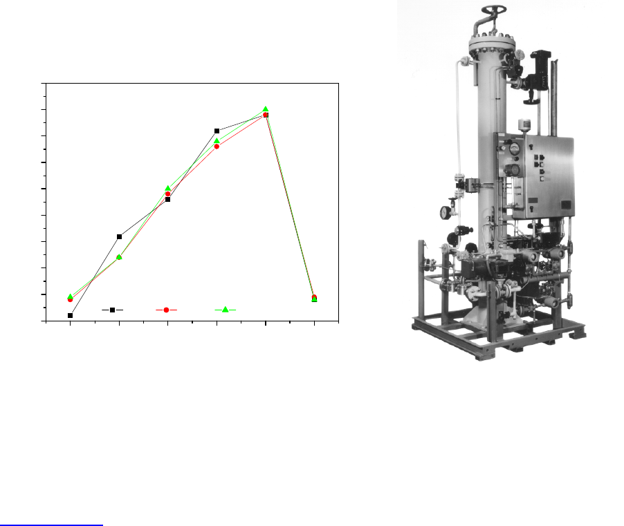
APPLICATIONS
Backwash Filter Performance: Case Study 1
Pilot studies at a commercial refinery used a 10
GPM (340 BPD) automated pilot filter
(Figure 5) to verify filter operating perf
ormance and media selection in tests conducted
during a two
-
month trial. The filter was cycled continuously between filtration and
backwash, with more than 2500 cycles performed. Backwash liquid was intermediate
cycle gas oil. Tests were conducted to maxi
mize the number of cycles during the test
period.
Figure 6 shows a uniform pressure profile comparing the rate of rise in pressure drop
over time of grade 2 media after 1, 4 and 30 days. Slurry oil concentration ranged from
500
-
1000 PPM. Average particle
size was about 20 µm. The filtration cycle was about
40 minutes with terminal pressures of 37
-
40 PSI. Recovery pressure after backwash
ranged from 2
-
5 PSI. Filtrate quality was less than 25 PPM TSS with most cycles < 10
ppm or less.
Increase in solid
s concentration will shorten cycle time as pressure drop increases at a
faster rate. This effect can be overcome somewhat by increasing the cycle terminal
pressure drop. If the increased solids concentration is due to the addition of large
particles increa
sed solids cake permeability may
result, which will increase the solids loading capacity
at the same pressure drop.
Figure 6. Pressure profile comparison
Figure 5. Automated Filter

www.mottcorp.com
10
Mott Corporation
Table
4
. Filtration cycle time and backwash sequence
Backwash Sequence Description
Cycle Time
Filter forwar
d flow to 60 PSID
80 minutes
Drain Filtrate Shell
1.5 minutes
Fill with LCO
1.5 min
Pressurize
0.25 minutes
Backwash and Drain
0.25 minutes
Total Time
83.5 minutes
Filter Operating Efficiency: Case Study 2
Online and throughput efficiency of
backwashable sintered metal filter were evaluated
using both full shell and empty (drained) shell backwash methods using an automated
filter system. The filtration unit consists of 24” diameter filter housing with standard 2”
diameter elements, having a to
tal filtration area of 174 ft
2
. Filter operation parameters
were 40 GPM with solids load to filter of 0.75#/min. Filter design operating flux is 0.23
gpm/ft
2
. The filter cycle time and backwash sequence is described in Table 4.
Filter efficiency is also
measured as throughput efficiency, or amount of product
processed as filtrate compared to the amount of product or feed delivered to the filter.
This is defined as:
E
T
=(V
FIL
/ V
FD
) x 100%
Where: E
T
= efficiency of liquid recovery
V
FIL
= volume
of filtrate recovered
V
FD
= volume of feed to the filter
Online efficiency is measured as forward flow cycle time divided by entire filtration cycle
time (including backwash) or 80/83.5 x 100 = 95.8% efficiency.
The filtration unit is designed to minimi
ze loss of product, which consists primarily of the
backwash and recovered solids. Throughput efficiency comparing full shell and drained
shell backwash is described in Table 5. The total volume processed (40 GPM x 80
minutes) was 3200 gallons.
Table
5
. Throughput Efficiency
Full Shell
Drained Shell
Backwash Volume, gallons
150
70
(V
FIL
/ V
FD
)
3050/3200
3130/3200
Throughput Efficiency
95 %
98%

www.mottcorp.com
11
Mott Corporation
Figure 7. Schematic of triple filter system
Filter Operating Experience
–
Commercial Installations
In 1985, the first cont
inuous use of a sintered metal filter using inside
-
out (LSI)
HyPulse
®
filtration technology developed by Mott Corporation demonstrated the
suitability of sintered metal media for high temperature filtration of slurry oil for a carbon
fiber development proc
ess. Slurry oil came from tankage where large particles had
settled and oil had cooled to 350°F, increasing the viscosity to 9 cp. The filter operated
reliably for many years producing clean oil with solids content of less than 20 ppm. The
filter was even
tually shut down because of low product demand.
Since then, refineries around the world have become aware of the benefits of filtration
using sintered metal media for catalyst fines removal in slurry oil service. The largest
systems to date are located i
n the United States and China.
Throughout the 1990’s numerous LSI filtration systems have been installed for FCC
slurry oil filtration at numerous refineries worldwide the largest employing (3) 66” LSI
filters. A schematic of a triple filter system is sh
own in Figure 7. Filtration cycle time
ranges from 2 to 16 hours operating at 30 & 60 PSI, respectively in the filtration of 1000
ppm slurry oil. Extended cycle times were obtained by running two filters
simultaneously, but staggered in cycle time, with th
e third being on stand
-
by for
utilization when one of the other filter units is backwashed. The filter design uses a full
shell backwash. Efficiency of the recovered product using two filters on line exceeds
99.8%
9
.
Since 1997, several refineries in Chi
na
have installed LSI filtration systems for
catalyst removal in resid fluid catalytic
cracking (RFCC) units. A filtration
system with (2) 24” LSI filters was
installed in a RFCC unit with 1.4 million
metric tons (mt) per year capacity and an
output of sl
urry oil of 180 mt/day. The
filter is controlled by local PLC that
communicates with refineries distributed
control system (DCS) to enable the
operator monitor the filtration in the
control room. The slurry oil has an
average 3,000
-
5,000 ppm solids
concent
ration. Cycle time varies from 2
-
8
hours. The filtrate solids content is under
50 ppm. The system is running
continuously since then supplying a local company with clean filtrate to produce carbon
black.
Another unit has 1.2
-
million mt/year capacity but on
ly has about 75
-
mt/day slurry oil
output. The system utilizes (3) 20” LSI filters controlled by local PLC. Each filtration unit
is capable of handling entire flow, or two filters can run simultaneously to optimize

www.mottcorp.com
12
Mott Corporation
product yield. The unit operates mostly du
ring the winter months to supply the clean
slurry oil to replace fresh crude as fuel oil for heating in the oilfield and local residential
area. Average slurry oil concentration is 4,000
-
6,000 ppm, and is occasionally over
10,000 ppm under unstable conditi
ons. Cycle time varies from 30 minutes to 4 hours
depends on the operating conditions and solids concentration.
SUMMARY
Sintered metal media has demonstrated its suitablity in a highly efficient catalyst
removal filter system for slurry oil service. Com
mercial FCC installations using grades
0.5 and 2 media are capable of producing quality clean oil product with suspended
solids content of less than 20 PPM. Filtrate quality of RFCC is typically about 50 ppm.
Filtration offers a slurry stream of higher pr
oduct value that can be used as a clean fuel
blend component, feed stock for needle coke or high
-
grade carbon black slurry oil
stream.
Filtration utilizing a unique housing configuration that allows feed to be fed to the inside
of the filter cartridge op
timizes both operating efficency and backwash efficiency of the
filter.
Proper media selection, along with filtering within specified operating parameters,
provides product recovery up to 99.8% efficiency. The inside
-
out filter configuration
minimizes back
wash volume that is either recycled back to the reactor or handled as a
waste product. Backwash volume is 0.5 to 1 gal/ft
2
, depending on whether filtrate is
drained from the shell or used as backwash. On a capacity basis, for 1000 BPD
processed, 20
-
50 BPD
go back to the reactor as backwash. This is a low rate in
comparison to other types of backwash filters used in this application.
A benefit of the filter system design is the scale
-
ability of the filtration unit to handle high
flow rates and solids cap
acities without complicated changes to hydralic flows. Filtration
systems are
suitable for both batch and continuous processes. Optimum sizing and high
pressure drop capacity result in quick filter turnaround.
REFERENCES
1
Mott Technical Bulletin,
FCC Slurry Oil Filtration with Mott Hypulse® LSI Filters
,
www.mottcorp.com
.
2
Hastelloy is a registered trademark of Hayes
International Inc.
3
Inconel and Monel are registered trademarks of International Nickel Co., Inc.
4
Allen, Jackman and Powell,
Petroleum Refining Industry Waste Audit
, page 204, May 1990.
5
Akzo Nobel Technical Information Bulletin,
Advanced FCC Fines
Analysis
,
www.akzonobel
-
catalysts.com
.
6
Mott Technical Bulletin,
Porous Metal as a Filter Medium.
7
U.S. Patent #4,552,669, R.S. Sekellick, assigned to Mott Metallurgical Corp., November 1985.
8
Mott Technical Handbook,
Porous Metal Technology in Liquid/
Solids Separation,
Section 9.
9
Mott Technical Bulletin,
Recent Advancements in FCC Slurry Oil Filtration with Mott HyPulse LSI Filters.
