
Page 1
AS322535
Rendering your Revit project with 3ds Max Arnold –
The Basics
Jean-Pierre van Gastel
Tech Data – Datech Solutions
Description
During this presentation, you’ll learn how to start using the Arnold rendering engine that is part
of 3ds Max software. Lighting is a crucial element in architectural design. Based off an imported
Revit file, you’ll learn what kinds of lights Arnold offers to help tell the story of your design.
Besides exploring different Arnold lighting techniques, you’ll get a much better understanding of
the most important Arnold render settings. This will include the advantage of NVIDIA’s RTX-
based technology, which will help denoise your image in a split second. We’ll also explain the
Arnold standard surface material to give you a much better understanding of the next step in the
world of 3ds Max materials. The presentation will end with some smart vegetation techniques
that don’t slow down your Arnold rendering at all.
Speaker(s)
I started using Autodesk products twenty-seven years ago. After learning AutoCAD 12 and 3D
Studio DOS version 3.0 I started my long career as an AutoCAD draftsman. I became part of
Autodesk distribution in 1995 and started delivering technical training and support for AutoCAD
and 3D Studio resellers in the Benelux region. As it is today, I’m still part of Autodesk
distribution and I do support Autodesk and the Autodesk resellers in Benelux, UKI and the
Nordics. 3ds Max is the product where I’m currently focusing on.
Learning Objectives
• Learn how to setup the Arnold render engine in 3ds Max
• Learn how to render imported Revit lights and how to control the quality
• Learn how to denoise your rendered images utilizing NVIDIA’s RTX technology
• Learn about the Arnold Standard Surface parameters

Page 2
Contents
Rendering your Revit project with 3ds Max Arnold – The Basics ................................................ 1
Common Parameters in the Render Setup Dialog box ........................................................ 4
Arnold Renderer settings .................................................................................................... 5
3ds Max Scene Converter ..................................................................................................11
Arnold Buddy Script ...........................................................................................................12
Solving different errors/warnings ........................................................................................12
3ds Max Physical Camera Exposure Control .....................................................................16
VFB+ Render Frame Window Script ..................................................................................17
3ds Max ActiveShade in 3ds Max 2020 Floating Viewport .................................................18
Arnold Lights ......................................................................................................................18
Shader Override in Arnold 3.2.57 .......................................................................................19
Arnold Skydome Light ........................................................................................................20
Arnold Quad Light ..............................................................................................................28
Arnold Distant Light ............................................................................................................29
Arnold Cylinder Light ..........................................................................................................30
Arnold Disk Light ................................................................................................................30
Arnold Photometric Light ....................................................................................................31
Arnold Point Light ...............................................................................................................31
Arnold Spotlight..................................................................................................................32
Arnold Mesh Light ..............................................................................................................33
OptiX™ Requirements .......................................................................................................34
Apply on Beauty .................................................................................................................35
OptiX GPU denoiser in ActiveShade ..................................................................................37
Arnold CPU Denoiser .........................................................................................................40
Getting Started with Arnold GPU ........................................................................................46
Matching Noise on CPU and GPU .....................................................................................48
Textures .............................................................................................................................49
ActiveShade GPU Denoising .............................................................................................49
Physical Materials vs Arnold Standard Surface ..................................................................50
Arnold Standard Surface ....................................................................................................50
Energy Conversation .........................................................................................................51
Standard Surface Basic Parameters ..................................................................................51
Specular Reflections ..........................................................................................................52

Page 3
Transmission .....................................................................................................................58
Sub-Surface Scattering ......................................................................................................63
Emission ............................................................................................................................67
Thin Film ............................................................................................................................68
Special Features ................................................................................................................69
Sheen ................................................................................................................................69
Coating ..............................................................................................................................71
Coat Normal (Bump) ..........................................................................................................72
3ds Max tools and scripts ...................................................................................................75

Page 4
Learn how to setup the Arnold render engine in 3ds Max
The Arnold render engine is included in 3ds Max since 3ds Max version 2018, although it’s not
set as the default renderer. To change the 3ds Max renderer to Arnold you’ll need to open the
Render Setup dialog box (F10). For best practices you should both set the Production Render
and the Active Shade to Arnold.
Both Production and ActiveShade mode set to the Arnold render engine
Common Parameters in the Render Setup Dialog box
In the Command Parameters tab, you won’t find any Arnold specific parameters. The two most
important options are the Time Output (Single frame or Active Time Segment) and the Output
Size (resolution of the rendered image). I’d like to set the output size to 1280 x 720 for test
renders but that’s just a personal preference.

Page 5
Arnold Renderer settings
In the Arnold Renderer tab in the Render Setup dialog box you’ll find the most important Arnold
render settings.
MAXtoA Version
The currently installed version of the Arnold renderer is showed in the MAXtoA Version
rollout. If there’s a new version available you’re able to click on the new version link
which will point you to the www.arnoldrenderer.com website. Arnold is a plug-in so
there’s no need to completely uninstall 3ds Max. Installing the updated Arnold plug-in will
do.

Page 6
Sampling and Ray Depth roll-out
In the Sampling and Ray Depth roll-out in the Arnold Renderer tab you control the quality
of the rendered image. Quality is expressed in samples and higher samples will yield
into better quality (less noise) but longer render times.
Camera (AA) samples
Supersampling control over the number of rays per pixel that will be traced from the
camera. The higher the number of samples, the better the anti-aliasing quality, and the
longer the render times. The exact number of rays per pixel is the square of this value.
For example, a Camera (AA) samples value of 3 means 3x3 = 9-pixel samples. In
practice, you may consider using a value of 4 for medium quality, 8 for high quality,
and (rarely) 16 for super-high quality. This control acts as a global multiplier of all the
different rays, multiplying the number of Diffuse and Specular rays. Motion blur and
depth of field quality can only be improved by increasing Camera (AA) samples.
Camera (AA) samples multiply Diffuse, Specular, and light samples after being
squared. For example, 6 Camera (AA) samples and 6 Specular samples = 6
2
x 6
2
=
1296 rays per pixel for the Diffuse, and another 1296 rays per pixel for the indirect
specular. Therefore, when you increase the Camera (AA) samples to get better
geometric anti-aliasing, you should decrease the others to compensate.
Diffuse samples
Controls the number of rays fired when computing the reflected indirect radiance
integrated over the hemisphere. The exact number of hemispherical rays is the square
of this value. Increase this number to reduce the indirect diffuse noise. Remember that
the diffuse sampling is done for each Camera (AA) sample, so high values for both
Camera (AA) samples and Diffuse samples will tend to result in slow renders. When
Diffuse samples are more than zero, camera rays intersecting with diffuse surfaces fire
indirect diffuse rays. The rays are fired in random directions within a hemispherical
spread. Noise is introduced when there are insufficient rays to resolve the range of
values from the environment. Increasing the number of Diffuse samples will increase the
number of diffuse rays fired from a point.

Page 7
Specular samples
Controls the number of rays fired when computing the reflected indirect radiance
integrated over the hemisphere weighted by a specular BRDF. The exact number of rays
is the square of this value. Increase this number to reduce the indirect specular noise
(soft/blurry reflections). Remember that the specular sampling is done for each Camera
(AA) sample, so high values for both Camera (AA) samples and Specular samples will
tend to result in slow renders.
Transmission samples
Controls the number of samples used to simulate the microfacet-based transmission
evaluations. Increase this value to resolve any noise in the transmission.

Page 8
If you switch this parameter to zero, the GI_transmission_depth to zero and the noise
disappears, you will know that the noise is due to transmission.
Sub Surface Scattering samples
This value controls the number of lighting samples (direct and indirect) that will be taken
to estimate lighting within a radius of the point being shaded to compute sub-surface
scattering. Higher values produce a cleaner solution but will take longer to render.
Diffuse Ray Depth
Defines the maximum ray diffuse depth bounces. Zero Diffuse is equal to disabling
diffuse illumination. Increasing the depth will add more bounced light to the scene, which
can be especially noticeable in interiors. You may notice subtle differences when
increasing the diffuse bounces incrementally.

Page 9
Specular Ray Depth
Defines the maximum number of times a ray can be specularly reflected. Scenes with
many specular surfaces may require higher values to look correct. A minimum value of 1
is necessary to get any specular reflections.
Transmission Ray Depth
The maximum number of times a ray can be refracted. Scenes with many refractive
surfaces may require higher values to look correct.

Page 10
Learn how to render imported Revit lights and how to control the quality
When you import a native Revit (.rvt) file in 3ds Max you automatically get a daylight system in
your 3ds Max scene called Sun Positioner. The Sun Positioner itself holds the day, time,
location etc. based on the settings you make in Revit. The most important part of the Sun
Positioner is the Physical Sun & Sky Environment which is nothing else then a High Dynamic
Range Image (HDRI) placed in the Environment slot of 3ds Max. The Arnold renderer can
render the Sun Positioner without any conversion.
Physical Sun & Sky Environment in the Environment and Effects dialog box (8)
Besides the Sun Positioner, 3ds Max will import Photometric Lights (.IES) from Revit. The 3ds
Max Revit importer supports parallel processing since 3ds Max 2019.3 which speeds up the
import process a lot. With regards to materials it’s important to use the 3ds Max Scene
Converter otherwise the imported Autodesk materials won’t render with Arnold and you do get a
lot of warnings.

Page 11
Warnings in the Render Message Window about the Autodesk materials
3ds Max Scene Converter
The 3ds Max Scene Converter, found in the Rendering menu converts all the Autodesk
materials into Physical materials. Physical materials are compatible with the Arnold render
engine. When you decide to use the Scene Converter, based on default settings the 3ds Max
render engine will be set to the ART rendering engine and you must change the render engine
back into the Arnold render engine.
The 3ds Max Scene Converter dialog box

Page 12
Arnold Buddy Script
You can easily speed up the render setup process by using a free script called Arnold Buddy.
The Arnold Buddy script will automatically set both Production and Active Shade to Arnold.
The Arnold Buddy script
Solving different errors/warnings
After utilizing the 3ds Max Scene converter you still might get some errors about Legacy maps
(Autodesk Bitmap and Autodesk Noise) which is not supported. If this is the scenario you can
enable Legacy 3ds Max Map Support in de System tab in the Arnold Render Setup.
Legacy 3ds Max Map support enabled in the Arnold Render Setup

Page 13
In case you get a warning about empty bitmaps, probably a Bitmap map type is present in one
or more Material Slots, but no specific bitmap file has been loaded. If the render stops after the
Preview pass and does not continue, then the "Abort on Error" switch has been turned on
(usually after an Arnold update) in the Diagnostics tab of the Arnold Render Setup dialog box.
This checkbox is turned on by default. If you switch it off your 3ds Max scene will always render
despite missing Bitmaps.
Abort on Error switched off in the Diagnostics tab of the Arnold Render Setup
When you render a 3ds Max scene with a Sun Positioner you might see some fireflies in the
rendered image. Fireflies are mostly caused by the bright sun disc from the Physical Sky
shader.

Page 14
Fireflies can be hard to remove, clamping will help a lot
This kind of noise is difficult to remove by simply increasing the number of samples in the
Render Setup. A simple way to remove them is to use Clamping which can be found in the
Arnold Renderer tab of the Arnold Render Setup.

Page 15
Indirect Max Value set to 1.0 to reduce fireflies

Page 16
Firefly reduced after using Clamping option in the Arnold Render tab
3ds Max Physical Camera Exposure Control
When you think the Arnold rendered image is too dark or too bright you may have to adjust the
Physical Camera Exposure Control. When a Physical Camera is the active camera you define
the exposure in the camera properties. If your view is set to a Perspective view you need to set
the right exposure value in the Exposure dialog box. ActiveShade mode with Arnold is the most
interesting one since adjusting exposure doesn’t re-render but is just tone mapping the render
frame window in real-time.

Page 17
VFB+ Render Frame Window Script
If your using the free VFB+ script you’re able to adjust the exposure control directly in the
Render Frame Window when doing a production render.
VFB+ provides additional great tools in the 3ds Max Render Frame Window

Page 18
3ds Max ActiveShade in 3ds Max 2020 Floating Viewport
If you want to interact with the 3ds Max scene in ActiveShade mode, you can start a floating
viewport which is available since 3ds Max 2020.1 In the floating viewport you can set the 3ds
Max viewport to ActiveShade.
Floating viewport in 3ds Max 2020.1 with the Arnold Active Shade running
Arnold Lights
If you want to change the imported Revit lights in your 3ds Max scene you should start using
Arnold lights. Arnold provides just one light, but it has many different types. Before you start
placing different Arnold light types it’s a best practice to remove the Physical Sun & Sky
Environment shader from the 3ds Max environment dialog box. This can be done by just
unchecking the option Use Map or the option Clear available in the right click menu.

Page 19
Disabling the Physical Sun & Sky Environment
When disabling the Physical Sun & Sky Environment shader you’re disabling all the lights in 3ds
Max viewport since the Sun Positioner object itself is not a light source.
Shader Override in Arnold 3.2.57
Before you start creating Arnold lights it’s a best practice to use the new Shader Override option
introduced in Arnold 3.2.57. The Shader Override can be an Arnold Standard Surface or
Physical Material. The base color of the material should be neutral (grey) without any
reflections. With the Shader Override applied you can focus completely on the lights setup and
you won’t be distracted by the different materials/textures in the 3ds Max scene. From the
Material Editor you’re able to drag the material into the Shader Override option found in the
Diagnostics tab of the Arnold Render Setup.
Shader Override applied in Arnold 3.2.57

Page 20
It’s also recommended to create a dedicated Lights layer which can be used to place the
different Arnold light types.
Arnold Skydome Light
The Arnold Skydome Light simulates light from a hemisphere or dome above the scene,
representing the sky. It doesn’t matter where you place the Arnold Skydome Light in the 3ds
Max scene. After placing the Skydome Light in the 3ds Max viewport your rendered image is
probably way too bright due to the default high intensity of the Skydome Light. Changing the
Exposure value of the Skydome Light to a lower value will lead into a better balance in the
exposure.
Changing the Exposure value parameter in the Arnold Skydome Light to 1.0

Page 21
If your rendered image is still too bright you might need to change the global exposure control of
the camera or perspective view. The 3ds Max ActiveShade mode is your best friend for
achieving the right balance in light intensity vs global exposure control. The Skydome Light itself
is not visible by default. Activating the Light Shape Visible option will make the Skydome Light
visible in the background.
Light Shape Visible option checked in the Shape roll-out parameters of the Skydome Light
If you don’t like the default white color of the Skydome light you can change the RGB color, use
one of the provided presets, change the Kelvin temperature color or use a texture (HDRI) in the
Texture option of the Skydome.

Page 22
Default color of the Skydome light with the Arnold Shader Override applied

Page 23
Default color of the Skydome light with the Arnold Shader Override disabled
Using an HDRI (High Dynamic Range Image) in the 3ds Max environment is often called Image
Based Lighting. You can easily drag an .HDRI into the 3ds Max viewport and use it as an
environment. Simply adding an Environment Map automatically enables a Skydome light with
no other input required. The 'Skydome light' and background shader is constructed under the
hood, and no extra light creation is required.
Be sure that you drag and drop an .HDRI in an empty space of the 3ds Max viewport

Page 24
If you’re placing an .HDRI in the 3ds Max Environment slot you probably will get noise in the
specular highlights and soft shadows due to the default low sampling value. By using a higher
sample value in the Arnold Renderer tab of the Render Setup dialog box you can get rid of this
kind of noise.
3ds Max default sampling set to 1.0 for Environment gives poor quality in soft shadows and specular
highlights

Page 25
Samples set to 3 to get rid of noise in the specular highlights

Page 26
Rendered result with 3 Samples for Environment Lighting & Reflections
Instead of using an HDRI in the Environment I’d recommend using it as a texture in the Arnold
Skydome. It’s faster and you’ll have a bit more control. Keep in mind that if you load in a bitmap
texture into the Skydome light you’ll need to set the bitmap texture as a Spherical Environment
in the 3ds Max Material Editor. That can easily be done by dragging the bitmap into the Material
Editor. Double click on the bitmap will make the bitmap active so that you’ll get access to its
belonging parameters.
HDRI map set to Environment Mapping: Spherical Environment
The HDRI map normally in a longitude/latitude mode and the Skydome light must be set to this
option in the Shape roll-out of the light.

Page 27
Format of the Skydome light set to LatLong for HDR images
The resolution controls the detail of reflections of the Skydome. For most accurate results the
Skydome light resolution must be set to match the HDRI image resolution, however, in many
cases it can be set lower without a noticeable loss of detail in reflections. By default, the
parameter is set to 1000. The higher the resolution parameter, the longer the Skydome light will
take to precompute the importance tables for the light, which increase scene startup time.
The Portal Mode option is an important option if you’re rendering on the CPU only. In
combination with light portals (Quad Lights).
Interior Only blocks any light outside portals for interior only scenes.
Interior/Exterior lets light outside portals through for mixed interior and exterior scenes.
Off: turns off portals.
Blocking light outside portals more predictably reduces noise for interior only scenes.
The quality of the Skydome light is also based on samples and controlled in the Rendering roll-
out of the Skydome light.
Samples in the Skydome light properties

Page 28
Rendered scene with HDRI in the Skydome texture option. Light Shape Visible switched on
Arnold Quad Light
An Arnold Quad Light simulates light from an area source (a quadrilateral, specified by four
vertices). Can be used to model light from an extended source (fluorescent strip lights) or in
some circumstances from a window.
Arnold Quad Light with the Light Shape Visible checked
Skydome lights can use light portals to reduce noise for interior scenes, where the light comes
in through relatively small openings. Instead of emitting light, they can be used to guide
Skydome light sampling. Light portals must be placed to cover all windows, doors and other

Page 29
openings through which Skydome light comes into the scene. The light portal should be oriented
so that it is pointing in through the window.
Light portal pointing inwards outside window
Arnold Distant Light
This is a parallel light from a distant source, specified in terms of a direction vector. Often used
to model sunlight.
This light can be used to simulate sunlight coming through a window

Page 30
Adding an Arnold Distant light makes sense if you’re using an overcast HDRI in an Arnold
Skydome Light or in the Environment. Don’t use an HDRI with a sun in combination with an
Arnold Distant Light otherwise you’ll get two sunlight’s in your rendering which is just wrong.
Arnold Cylinder Light
The cylinder light shape simulates light from a cylindrical area source (tube shape).
Typically cylinder lights are used to simulate fluorescent tube lighting
Arnold Disk Light
The disk light shape simulates light from a circular area source (flat disk).

Page 31
Arnold Disk Light
Arnold Photometric Light
Photometric lights use data measured from real-world lights, often directly from bulb and
enclosure manufacturers themselves. You can import IES profiles from companies such as
Erco, Lamp, Osram, and Philips; their IES files provides accurate intensity and spread data for a
given light model.
Example IES lighting profiles
Arnold Point Light

Page 32
Although named point for historical reasons, this light source can model light either from a
(theoretical) point source, or from a sphere (the latter being more realistic in most cases and
producing fewer sharp shadows). The light is cast evenly in all directions.
Arnold Point Light
Arnold Spotlight
Simulates light from a spotlight, as a cone of light from the position of the light toward the point it
is pointed at.

Page 33
Arnold Spotlight
Arnold Mesh Light
In situations where conventional light shapes will not suffice, mesh lights are more
suitable. Mesh lights can be used to create interesting lighting effects that would not be possible
any other way. For example, effects such as neon lighting or a car light motion trail effect can be
achieved more easily with mesh lights.
Arnold Mesh Light renders clean

Page 34
It is not currently possible to make a mesh light visible to camera rays. A workaround is to add
Emission to a Standard Surface shader or Physical material assigned to the object. This will
give the impression that the geometry is incandescent. Set the Indirect Diffuse to 0 for the
Standard Surface shader assigned to mesh as the Mesh light is already emitting light.
Indirect Diffuse set to 0.0 in the Arnold Standard Surface shader
Learn how to denoise your rendered images utilizing NVIDIA’s RTX
technology
There are two denoising solutions available for rendering with Arnold.
The OptiX™ Denoiser (based on Nvidia AI technology), is integrated into Arnold for use
with ActiveShade. It can be applied to any AOV (Arbitrary Output Variable). The OptiX
denoiser is meant to be used during ActiveShade (so that you get a very quickly denoised
image as you're moving the camera and making other adjustments). For this reason, it is not
suitable for final frame rendering or animations as it can cause flickering between frames.
Reducing noise in an interior render is the biggest challenge. Typically, many Diffuse samples is
required to reduce the indirect noise in an interior. However, render times can increase
dramatically with high Diffuse samples.
OptiX™ Requirements
There are a couple of requirements to be aware of when using the OptiX denoiser, however:
1. You must have a Nvidia GPU with a driver version of at least 390 installed. Note that the
OptiX denoiser is not available on OSX.
2. The OptiX denoiser does not work with Merged AOVs (unlike the Arnold Denoiser).
3. If you want to use the OptiX denoiser on multiple AOVs you must apply it to each AOV.
4. If you wish to have the same AOV saved to EXR in both original and denoised mode, to
avoid name duplication you can add the suffix "_denoise" to the AOV name and the
OptiXdenoiser will detect the original AOV.
5. Depending on the scene size, you may have to lower the Min memory - Render Settings
> System > OptiX denoiser > Automatic Device Selection. This is also dependent on
how much memory you have on your GPU. The default settings act on the side of
caution and won't use your GPU if you have less than 512Mb available so that all GPU

Page 35
resources aren't used or worse try to use more memory than is available on the GPU.
Users can change this parameter at their own risk.
Apply on Beauty
When you activate the Apply on Beauty checkbox in the Denoiser tab of the Arnold Render
Setup, the denoiser is applied to the beauty pass without needing to create extra AOVs.
The OptiX Denoiser active in the Denoiser tab of the Arnold Render Setup

Page 36
Skydome light, Quad Light (portal mode), AA Samples:3 Diffuse samples: 3 OptiX Denoiser: off
Skydome light, Quad Light (portal mode), AA Samples:3 Diffuse samples: 3 OptiX Denoiser: on
Skydome light, Quad Light (portal mode), AA Samples:3 Diffuse samples: 6 OptiX Denoiser: off

Page 37
Skydome light, Quad Light (portal mode), AA Samples:3 Diffuse samples: 6 OptiX Denoiser: on
OptiX GPU denoiser in ActiveShade
If you want to utilize the OptiX denoiser in ActiveShade you’ll have to add an AOV in the
dedicated AOV’s tab of the Arnold ActiveShade Mode Render Setup.
AOVs (Arbitrary Output Variables) provide a way to render any arbitrary shading network
component into different images. For example, an artist might find it convenient to separate
direct and indirect lighting contributions and later recombine them during compositing. Arnold
provides built-in AOVs for outputting depth, position, and motion vectors.
The exact AOV you’ll mostly need for denoising in the ActiveShade and rendering on the CPU,
is the built-in RGBA AOV which can be found when activating the Add AOV File button.

Page 38
The built-in RGBA AOV when rendering on the CPU
When selecting the RGBA AOV you’ll click on the lower left button called Add to add the AOV to
the list. Be sure to select the RGBA AOV in the list after adding the AOV and double check if the
Data is set to rgba and activate the Denoise with OptiX checkbox.

Page 39
Denoise with OptiX option checked for the RGBA AOV
When the ActiveShade is running you can access the RGBA denoised AOV in the dedicated
dropdown section of the ActiveShade.

Page 40
RGBA Denoised AOV active in the ActiveShade Render Mode
Arnold CPU Denoiser
The Arnold Denoiser can be run from a dedicated UI, exposed in the Denoiser. It favors quality
over speed and is, therefore, more suitable for high-quality final
frame denoising and animation sequences. To use the Arnold denoiser, you’ll need to render
images out first via the Arnold EXR driver with variance AOVs enabled. It is also available as a
stand-alone program (noice.exe).
The workflow is as follows:
1. Go to the Denoiser tab in the Arnold Render Setup and enable Output Denoising AOVs.
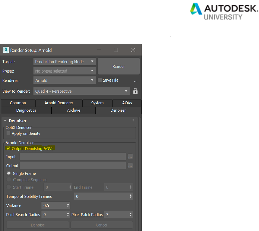
Page 41
Output Denoising AOVs option in the Denoiser tab of the Arnold Render Setup
2. Ensure that you are rendering out to an EXR file format. You can do this by activating
the Save File option in the upper right corner of the Arnold Render Setup. The default
options of the EXR file format are fine.

Page 42
Save File must be checked for saving a render to an EXR file format
Save as Type set to OpenEXR Image File

Page 43
The default settings of the OpenEXR Configuration
3. Render the scene. Alongside your beauty file, Arnold will save an EXR version of it, also
containing the AOVs needed for denoising. They are named after the beauty filename,
post fixed by "_Noice_Input".

Page 44
The Noise_Input EXR file format needed for the Denoiser
4. Go to the Denoiser tab.
5. Choose a rendered _Noice_Input EXR image in the Input and a directory for the output
(denoised) files.

Page 45
Input and Output Denoising set in the Denoiser tab of the Arnold Render Setup
6. Choose whether you want to denoise a single frame or a sequence and then select the
Denoise button.

Page 46
The Denoise button will start the CPU based denoising process
7. This will start the denoising process based on the settings that you have chosen. The
denoised images are saved in the output directory.
Getting Started with Arnold GPU
Arnold 5.3 and later includes a beta version of GPU-accelerated rendering. This beta feature is
known as "Arnold GPU". Arnold GPU is part of Arnold, so you can choose to render on the CPU
or GPU, without changing renderers. Arnold GPU is based on the NVIDIA OptiX framework and
is optimized to leverage NVIDIA RTX technology.
Supported Features
The Arnold GPU beta supports a set number of Arnold features, including arbitrary
shading networks, Sub Surface Scattering, hair, atmospherics, instancing, and
procedurals.
System Requirements

Page 47
Arnold GPU works on NVIDIA GPUs of the Turing, Volta, Pascal, and Maxwell
architectures. Multiple GPUs will improve performance, and NVLink can be used to
connect multiple GPUs of the same architecture to share memory (On Windows, we
recommend enabling SLI as well).
Recommended NVIDIA drivers
• Windows 430.86 or higher
Pre-populating the GPU cache
The very first time you render with the GPU, the GPU renderer has to create a cache of
shaders. This can delay the time to first pixel for your first render.
To avoid the one-time delay, we recommend that you run Pre-Populate GPU
Cache before you do any renders. Note that pre-populating the cache can take up to 15
minutes.
The cache only needs to be re-populated after installing a new Arnold version, updating
to a new NVIDIA driver, or changing the hardware configuration of GPUs on the system.
Pre-populate GPU Cache found in the System tab of the Arnold Render Setup

Page 48
Selecting a Render Device
You can easily switch between CPU and GPU with a single click in the System render
settings.
Render Device set to GPU (BETA)
Matching Noise on CPU and GPU
Matching noise can take a little experimentation because Arnold GPU uses Camera
(AA) sampling only. We recommend you also use Adaptive sampling. Here are some
guidelines:
• Set the Max. Camera (AA) in the range of 30 to 50 (depending on the scene, you might
go closer to 100). In general, the max samples should be a large value. A large max
sample means that the quality is controlled by the noise falling under the threshold,
instead of by clamping to the max AA.

Page 49
• Set the Adaptive Threshold to something like 0.015 or 0.02. For a noise-free render,
lower the threshold value, maybe even as far as 0.010.
• Set the Camera (AA) samples to around 3 or 4. One of the few reasons to go higher with
AA is for motion blur. The higher the number of Camera (AA) samples, the less of a
speedup you'll get from adaptive sampling.
Adaptive and Progressive checked for Arnold GPU rendering
Textures
All textures must fit in memory. If you're running out of memory, you can set a maximum
resolution for textures in the Render Settings.
ActiveShade GPU Denoising
If you want to denoise in Active Shade when rendering on the GPU, you’ll need to add the
RGBA_denoise AOV in the AOVs tab in the Arnold Render Setup.

Page 50
RGBA_denoise AOV is used by the ActiveShade mode on GPU
Learn about the Arnold Standard Surface parameters
Physical Materials vs Arnold Standard Surface
The 3ds Max Physical Material is supported in Arnold. It translates to the
Arnold Standard Surface shader behind the scenes. However, not all of its features are fully
supported, notably the "advanced" mode with a custom reflection curve.
It is effectively functionally equivalent to the Arnold Standard Surface, but using it has the
benefit of being renderer agnostic, having a nicer UI, and having a good viewport
representation.
Arnold Standard Surface

Page 51
The Standard Surface shader is a physically based shader capable of producing many types of
materials. It includes a diffuse layer, a specular layer with complex Fresnel for metals, specular
transmission for glass, subsurface scattering for skin, thin scattering for water and ice, a
secondary specular coat, and light emission.
Energy Conversation
Standard Surface is energy conserving by default. All its layers are balanced so that the amount
of light leaving the surface does not exceed the amount of incoming light. For example, as a
surface is made more metallic and the specular layer contribution is increased, the diffuse layer
contribution is reduced accordingly to ensure energy conservation.
Diffuse and rough (left) to metallic specular (right).
Standard Surface Basic Parameters
Base Weight
The base color weight (default is 0.8).
Base Color
The base color sets how bright the surface is when lit directly with a white light source
(intensity at 100%). It defines which percentage for each component of the RGB
spectrum which does not get absorbed when light scatters beneath the surface. Metal
normally has a black or very dark base color; however, rusty metal's need some base
color. A base color map is usually required.

Page 52
Roughness
The base component follows an Oren-Nayar reflection model with surface roughness. A
value of 0.0 is comparable to a Lambert reflection. Higher values will result in a rougher
surface look more suitable for materials like concrete, plaster or sand.
Specular Reflections
Weight
The specular weight. Influences the brightness of the specular highlight.

Page 53
Color
The color the specular reflection will be modulated with. Use this color to 'tint' the
specular highlight. You should only use colored specular for certain metals, whereas
non-metallic surfaces usually have a monochromatic specular color. Non-metallic
surfaces normally do not have a colored specular.
Roughness
Controls the glossiness of the specular reflections. The lower the value, the sharper the
reflection. In the limit, a value of 0 will give you a perfectly sharp mirror reflection, while
1.0 will create reflections that are close to a diffuse reflection. You should connect a map
here to get variation in the specular highlight.

Page 54
The 'microscopic' features of a surface affect the diffusion and reflection of light. This
'micro surface' detail has the most noticeable effect on specular reflections. In the
diagram below, you can view parallel lines of incoming light commence to diverge when
reflected from rougher surfaces when each ray hits a part of the surface with a different
orientation. In summary, the rougher the surface becomes, the more the reflected light
will diverge or appear 'blurred.'
'Microsurface' detail represented as a general measure of roughness
(this surface would have a high Specular Roughness value).
The brightness of the Specular highlight is automatically linked to its size due to the
Standard Surface Surface shader's energy conserving nature. In the example below, all
of the materials are reflecting the same amount of light, but the rougher surface is
spreading it out in multiple directions. However, with low amounts of roughness, the
surface is reflecting a more concentrated amount of light.

Page 55
To get variation in the highlights of the surface, a map should be connected to the
Specular Roughness. This will influence not only the brightness of the highlight but also
its size and the sharpness of the environmental reflection.
Fingerprint texture -> Specular Roughness
The specular roughness affects both specular reflection and refraction. There is also
a Transmission Extra Roughness parameter to add some additional roughness for
refraction if required. You can, however, use Coat to create a rough reflection layer over
a sharp refraction.
Metalness
With metalness 1.0 the surface behaves like a metal, using fully specular reflection and
complex fresnel.

Page 56
For a perfectly sharp and mirror-like reflection, increase Metalness to 1 and reduce
Specular Roughness to 0. The Base Weight should also be set to 1.
When Metalness is enabled, the Specular Weight and Specular Color only control the
edge tint, while the Base is still affected by roughness.
The metal appearance is controlled using the Base Color (facing) and Specular Color
(edge tint) parameters. These are automatically translated to physical η and κ values, to
achieve the same look but with easily tweakable and texturable colors.
IOR
The IOR parameter (Index of Refraction) defines the material's Fresnel reflectivity and is
by default the angular function used. Effectively the IOR will define the balance between
reflections on surfaces facing the viewer and on surface edges. You can see the
reflection intensity remains unchanged, but the reflection intensity on the front side
changes a lot.
Using a very high IOR value can look quite similar to Metalness. It looks the same if you
set the Base Color to the Specular Color and the Specular Color to black. The difference
is that you get an extra reflection at the edges, with the Specular Color controlling the
edge tint. The metal fresnel works the same as in the new complex IOR shader, with the
artistic parameters.
You should normally use IOR for materials like plastic, glass, or skin (dielectric fresnel)
and Metalness for metals (conductive fresnel with Complex IOR). The other reason is

Page 57
that Metalness is easier to texture since it's in the 0..1 range and using textures from
applications like Substance painter works best when using Metalness rather than IOR.
Anisotropy
Anisotropy reflects and transmits light with a directional bias and causes materials to
appear rougher or glossier in certain directions. The default value for Anisotropy is 0,
which means 'isotropic.' As you move the control towards 1.0, the surface is made more
anisotropic in the U axis.
Anisotropy is suitable for materials that have a clear brush direction such as brushed
metal which has tiny grooves in which form a 'stretched' anisotropic reflection.
Anisotropic reflections are suitable for brushed metal effects.
Texture assigned to Anisotropic Rotation
Rotation
The rotation value changes the orientation of the anisotropic reflectance in UV space. At
0.0, there is no rotation, while at 1.0 the effect is rotated by 180 degrees. For a surface
with brushed metal, this controls the angle at which the material was brushed. For

Page 58
metallic surfaces, the anisotropic highlight should stretch out in a
direction perpendicular to the brushing direction.
Transmission
Weight
Transmission allows light to scatter through the surface, for materials such as glass or
water.
Color
This filters the refraction according to the distance traveled by the refracted ray. The
longer light travels inside a mesh, the more it is affected by the Transmission Color.
Therefore, green glass gets a deeper green as rays travel through thicker parts. The
effect is exponential and computed with Beer's Law. It is recommended to use light,
subtle color values.
Depth
Controls the depth into the volume at which the transmission color is realized. Increasing
this value makes the volume thinner, which means less absorption and scattering. It is a

Page 59
scale factor so that you can set a transmission color and then tweak the Depth to be
appropriate for the size of your object.
Depth is scene scale dependent and can have a dramatic effect on its appearance. The
Transmission Color and Depth control transmittance/absorption, and that depends on
the object scale. So, for a small object to see anything you might need to set a quite low
Depth, or for a big object a high one. If you cannot see the effect of Depth, then you may
need to check the size of your scene.
Thin Walled
Thin Walled can also provide the effect of a translucent object being lit from behind (the
shading point is 'lit' by the specified fraction of the light hitting the reverse of the object at
that point). It is recommended that this only be used with thin objects (single sided
geometry) as objects with thickness may render incorrectly.

Page 60
Extra Roughness
Adds some additional blurriness of refraction computed with an isotropic microfacet
BTDF. The range goes from -1 to 1, where 0 means no roughness. It is computed as
Transmission Roughness = Specular Roughness + Transmission Extra Roughness.
Negative values result in a lower roughness for transmission than for reflection.

Page 61
Dispersion Abbe
Specifies the Abbe number of the material, which describes how much the index of
refraction varies across wavelengths. For glass and diamonds, this is typically in the
range of 10 to 70, with lower numbers giving more dispersion. The default value is 0,
which turns off dispersion. The chromatic noise can be reduced by either increasing the
global Camera (AA) samples or the Refraction samples.
Scatter
Color
Transmission Scatter is suitable for any liquid that is fairly thick or where there is enough
of it for scattering to be visible, such as a deep body of water or honey. If you have a

Page 62
glass of water, there is not that much scattering, however, for an ocean, it is required.
Other examples include materials like ice, opalescent glass or milky glass.
Scatter Anisotropy
The directional bias, or anisotropy, of the scattering. The default value of zero gives
isotropic scattering so that light is scattered evenly in all directions. Positive values bias
the scattering effect forwards, in the direction of the light, while negative values bias the
scattering backward, toward the light.

Page 63
Sub-Surface Scattering
Sub-Surface Scattering (SSS) simulates the effect of light entering an object and scattering
beneath its surface. Not all light reflects from a surface. Some of it will penetrate below the
surface of an illuminated object. There it will be absorbed by the material and scattered
internally. Some of this scattered light will make its way back out of the surface and become
visible to the camera. This is known as 'sub-surface scattering' or 'SSS'. SSS is necessary for
the realistic rendering of materials such as marble, skin, leaves, wax, and milk. The SSS
component in this shader is calculated using a brute-force raytracing method.
SSS is important when replicating realistic materials such as plastics.

Page 64
Weight
The 'blend' between diffuse and subsurface scattering. When set to 1.0, there is only
SSS, and when set to 0 it is only Lambert. In most cases, you want this to be 1.0 (full
SSS).
Color
The color used to determine the subsurface scattering effect. For example, replicating a
skin material would mean setting this to a fleshy color.
Scale
Controls the distance that the light is likely to travel under the surface before reflecting
back out. It scales the scattering radius and multiplies the SSS Radius Color.

Page 65
Radius
The approximate distance up to which light can scatter below the surface, also known as
“mean free path” (MFP). This parameter affects the average distance that light might
propagate below the surface before scattering back out. This effect on the distance can
be specified for each color component separately. Higher values will smooth the
appearance of the subsurface scattering, while lower values will result in an opaquer
look.
The lighter the color, the more light is scattered. A value of 0 will produce no scattering
effect.

Page 66
Type
Diffusion
With a single layer, it can capture both surface detail and deep scattering. Designed to
closely match the characteristics of the full Monte-Carlo simulation, while remaining an
approximation that's much cheaper to evaluate than a full Randomwalk.
Randomwalk (default)
Unlike the empirical BSSRDF method based on diffusion theory, the Randomwalk
method actually traces below the surface with a real random walk and makes no
assumptions about the geometry being locally flat. This means it can take into account
anisotropic scattering like brute-force volume rendering and produces much better
results around concavities and small details. It can also be substantially faster for large
scattering radius (i.e. large mean free path) compared to diffusion. On the other hand,
Randomwalk can be slower in dense media (i.e. small mfp), does not
support sss_setname for blending two surfaces together, may require redialing materials
to achieve a similar look, and is more sensitive to non-closed meshes, "mouth bags",
and internal geometry potentially casting shadows.
Randomwalk v2
This method scatters more accurately and deeply through highly transparent/optically
thin objects, which produces SSS with more saturated colors around fine surface detail
and heavily backlit regions of an object. Note that renders will be more costly and noisier
than with the original method since randomwalks will be on average longer and more
random.

Page 67
Anisotropy
Henyey-Greenstein Anisotropy coefficient between -1 (full backscatter) and 1 (full
forward-scatter). The default is 0 for an isotropic medium, which scatters the light evenly
in all directions, giving a uniform effect. Positive values bias the scattering effect
forwards, in the direction of the light, while negative values bias the scattering backward,
toward the light.
Emission
This attribute gives the appearance that the material is emitting incandescent light.
Emission
Controls the amount of emitted light. It can create noise, especially if the source of
indirect illumination is very small (e.g. light bulb geometry).

Page 68
Color
The emitted light color.
Thin Film
Thin Film reproduces the effect of thin film interference on a surface. It can be used for
materials, such as multitone car paint, burnt chrome or the reflective coating on a beetle
(Thickness: 400, IOR: 1.43).
Thickness
Defines the actual thickness of the film between the specified min and max thickness (0
to 2000 (soft min/max)). This affects the specular, transmission and coat components.
Normally this would be something like a noise map to give some variation to the
interference effect. If the thickness becomes large like 3000 [nm], the iridescence effect
will disappear, which is a physically correct behavior.
IOR
The refractive index of the medium surrounding the material. Normally this is set to 1.0
for air.

Page 69
Special Features
Opacity (Cutout)
Controls the degree to which light is not allowed to travel through it. Unlike
Transmission, whereby the material still considers diffuse, specular, etc., opacity will
affect the entire shader. Useful for retaining the shadow definition of an object, while
making the object itself invisible to the camera.
Sheen
Sheen Weight
An energy-conserving sheen layer that can be used to approximate microfiber, cloth-like
surfaces such as velvet and satin of varying roughness. Sheen is layered onto the
diffuse component and its weight is determined with this attribute. Sheen can be thought
of as the density or the combination of the density and length of the fibers.

Page 70
As well as fabric, Sheen can be used to simulate leaves, fruit or the peach fuzz on a face
(best when viewed from a distance).
Sheen Color
The color of the fibers. Tints the color of the sheen contribution.
Sheen Roughness
Modulates how much the microfibers diverge from the surface normal direction.

Page 71
Coating
Clearcoat
Weight
This attribute is used to coat the material. It acts as a clear-coat layer on top of all other
shading effects. The coating is always reflective (with the given roughness) and is
assumed to be dielectric. Examples would be the clear-coat layer for car paint or the
sheen layer for a skin material. For example, for an extra oily layer or wet skin. Other
examples would be objects that have been laminated or a protective film over an
aluminum cell phone.
The Coat layer simulates a dielectric (think plastic, glass, resin/enamel, many liquids)
which absorbs light and so tints all of the transmitted light (save maybe some very minor
polarization effects), while metals, on the other hand, tend to filter the color of whatever it
is they are reflecting, even at grazing angles. Therefore, if what you want to render a
bare metal, the Coat Weight should be 0.

Page 72
Color
This is the color of the coating layer's transparency.
Roughness
Controls the glossiness of the specular reflections. The lower the value, the sharper the
reflection. In the limit, a value of 0 will give you a perfectly sharp mirror reflection, while
1.0 will create reflections that are close to a diffuse reflection. You should connect a map
here to get variation in the coat highlight.
Coat Normal (Bump)
The Coat Normal affects the Fresnel blending of the coat over the base, so depending
on the normal, the base will be more or less visible from particular angles. Uses for Coat

Page 73
Normal could be a bumpy coat layer over a smoother base. This could include a rain
effect, a carbon fiber shader or a car paint shader where you could use different normals
(using e.g. flakes) for the coat layer and base layers.
When you specify a Coat Normal, it affects just the coat, and none of the layers below it
(diffuse, specular, transmission)..
IOR
The IOR parameter (Index of Refraction) defines the material's Fresnel reflectivity and is
by default the angular function used. Effectively the IOR will define the balance between
reflections on surfaces facing the viewer and on surface edges. You can see the
reflection intensity remains unchanged, but the reflection intensity on the front side
changes a lot.

Page 74
Affect Underlying
Color
In the real world, when a material is coated there is a certain amount of internal
reflections on the inside of the coating. This causes light to bounce onto the surface
multiple times before escaping, allowing the material's color to have an enhanced effect.
An example of this is varnished wood. This effect can be achieved by using Coat Affect
Color.
Roughness
This causes the coating's roughness to have an effect on the underlying layer's
roughness, simulating the blurring effect of being seen through the top layer.
In the example below, a checker texture has been connected to the Coat Roughness
with Metalness set to 1.0. When set to 0, the Coating is unaffected, whereas at 1 the
Coating Roughness is apparent.
Anisotropy
Anisotropy reflects and transmits light with a directional bias and causes materials to
appear rougher or glossier in certain directions. The default value for Anisotropy is 0,
which means 'isotropic.' As you move the control towards 1.0, the surface is made more
anisotropic in the U axis.

Page 75
3ds Max tools and scripts
3ds Max & Revit Essentials
https://www.autodesk.com/autodesk-university/class/3ds-Max-Revit-Softwares-Best-
Friend-2018
Arnold Buddy Script
https://www.dropbox.com/sh/mtms0mtzognsngc/AAClC33JR2XKjynUOhoUT1gba?dl=0
VFB+
http://www.monotoneminimal.com/vfb
HDRI
https://hdrihaven.com/
3D Sky
https://3dsky.org/
V-Ray to Arnold scene converter
https://www.masd.dk/arnoldconverter

